
Displayer lifting device

A lifting device and display technology, applied in the direction of lifting device, supporting machine, mechanical equipment, etc., can solve the problems of time-consuming adjustment process and failure to achieve the load-bearing capacity of the display.

Active Publication Date: 2015-07-15
TAIZHOU STRONKIN ELECTRONICS
View PDF7 Cites 7 Cited by
  • Summary
  • Abstract
  • Description
  • Claims
  • Application Information

AI Technical Summary

Problems solved by technology

However, when the user uses this adjustable lifting device that adjusts the force of the compression spring to adjust the force of the compression spring when assembling displays with different specifications and sizes, the adjustment process will be very time-consuming, and the result of the adjustment will be very time-consuming. It may also not be able to achieve the required weight capacity for the mounted monitor

Method used


Image

  • Displayer lifting device
  • Displayer lifting device
  • Displayer lifting device

Examples


Embodiment Construction

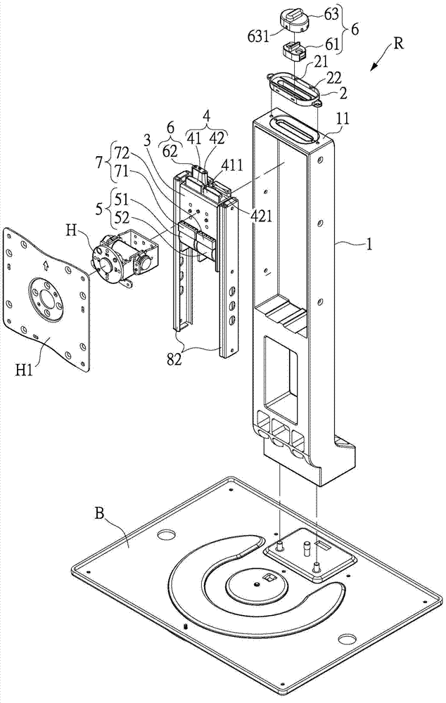
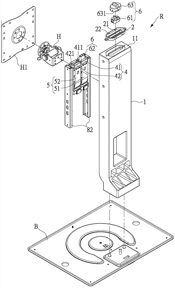
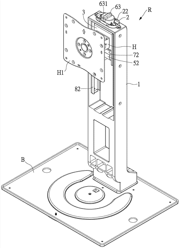
[0045] see Figure 1 to Figure 7 As shown, the embodiment of the present invention provides a display lifting device R, which includes a support frame 1, a limit seat 2, a bearing seat 3, a first clamping member 41, a second clamping member 42, a first The fixed force piece 51 , a second fixed force piece 52 and a switch 6 .

[0046] First, the support frame 1 is installed on the base B to support the support frame 1. The support frame 1 has a support surface 11, so that the limit seat 2 is arranged on the support surface 11. For example, the limit seat 2 can The design is integrally formed with the support frame 1, but the present invention is not limited thereto.

[0047] see Figure 4 and Figure 5 As shown, the bearing seat 3 is slidably arranged on the support frame 1. For example, the bearing seat 3 can slide on the support frame 1 through the setting of the track module 8. The track module 8 can have a pair of inner rails 81 With a pair of outer rails 82, the pair o...


PUM


Abstract

The invention discloses a displayer lifting device. The displayer lifting device comprises a supporting frame, a limiting seat, a bearing seat, a first clamping part, a second clamping part, a first anchoring force part, a second anchoring force part and a switching switch. The supporting frame is provided with a bearing face, and the limiting seat is arranged on the bearing face; the bearing seat is arranged on the supporting frame in a sliding manner; and the first clamping part and the second clamping part are arranged on the bearing seat. One end of the first anchoring force part is fixed to the first clamping part, and the other end of the first anchoring force part is connected with the bearing seat in a penetrating mode. One end of the second anchoring force part is fixed to the second clamping part, and the other end of the second anchoring force part is connected with the bearing seat in a penetrating manner. The switching switch is arranged on the limiting seat and is switched to the first position which is connected to the first clamping part so as to carry out action together with the first anchoring force part,, or the second position which is connected to the second clamping part so as to carry out action together with the second anchoring force part. According to the displayer lifting device, through position switching of the switching switch, the weight loading coincident with displayer weight bearing is achieved.

Description

technical field [0001] The invention relates to a lifting device, in particular to a display lifting device. Background technique [0002] In the past, in order to quickly adjust the position and height of the display according to different users, a single-standard lift-type display lifting device has been developed. It supports the weight of the display through the constant force spring in the lifting device. [0003] However, each display with different specifications and sizes has a different weight, and the heavier the weight, the spring with greater supporting force is required. Therefore, the existing lifting device for a display with a single specification can only be applied to a display with a single specification that corresponds to each other. . Therefore, whenever the specifications and sizes of the display are different, it is also necessary to cooperate with different single-size display lifting devices for assembly, but this will increase the manufacturing c...

Claims


Application Information

Patent Timeline
Patent Type & Authority Applications(China)
IPC IPC(8): F16M11/04B66F13/00
Inventor 魏庆昇罗煜清
Owner TAIZHOU STRONKIN ELECTRONICS
Learn More