Zoom lens and camera

A zoom lens and lens technology, applied in image communication, equipment, television, etc., can solve the problems of small chromatic aberration correction effect of the second lens group, insufficient wide-angle requirements, etc., to achieve good images and high magnification effect

Inactive Publication Date: 2017-04-05
FUJIFILM CORP
View PDF6 Cites 0 Cited by
  • Summary
  • Abstract
  • Description
  • Claims
  • Application Information

AI Technical Summary

Problems solved by technology

[0009] The zoom lens described in Patent Document 1 achieves high magnification, but the effect of correcting chromatic aberration of the second lens group is small
In addition, the angle of view on the wide-angle side is 65° or less, which is not sufficient for wide-angle use.
The zoom lens described in Patent Document 2 adopts a floating system, and although high performance can be achieved in the entire zoom range, the zoom ratio is about 54 times, and higher magnifications are expected in recent years.

Method used


Image

  • Zoom lens and camera
  • Zoom lens and camera
  • Zoom lens and camera

Examples


Embodiment 1

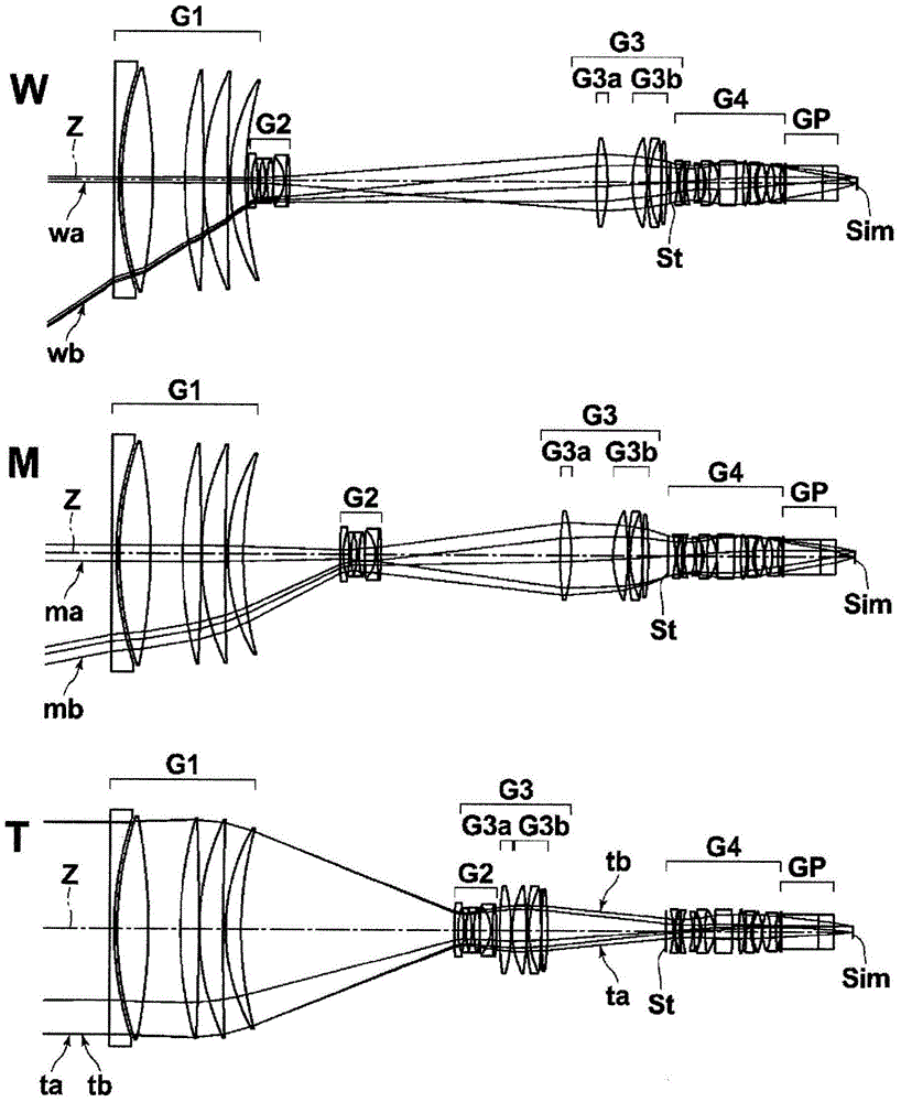
[0082] A cross-sectional view showing the configuration of the zoom lens of Example 1 is shown in image 3 middle. image 3 In , the upper, middle, and lower sections with marks W, M, and T on the left respectively show the arrangement and configuration of each lens group at the wide-angle end, intermediate focal length position, and telephoto end, respectively.

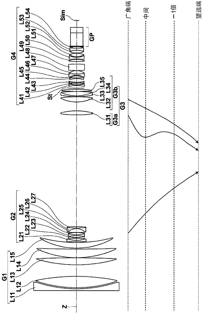
[0083] The schematic configuration of the zoom lens of Example 1 is as follows. That is, the zoom lens of Embodiment 1 consists of the first lens group G1 having positive refractive power, the second lens group G2 having negative refractive power, the third lens group G3 having positive refractive power, and the third lens group G3 having positive refractive power in order from the object side. The focal power of the fourth lens group G4 constitutes. The aperture stop St is arranged on the most object side of the fourth lens group G4. and also, image 3 The aperture stop St shown does not indicate its size and sh...

Embodiment 2

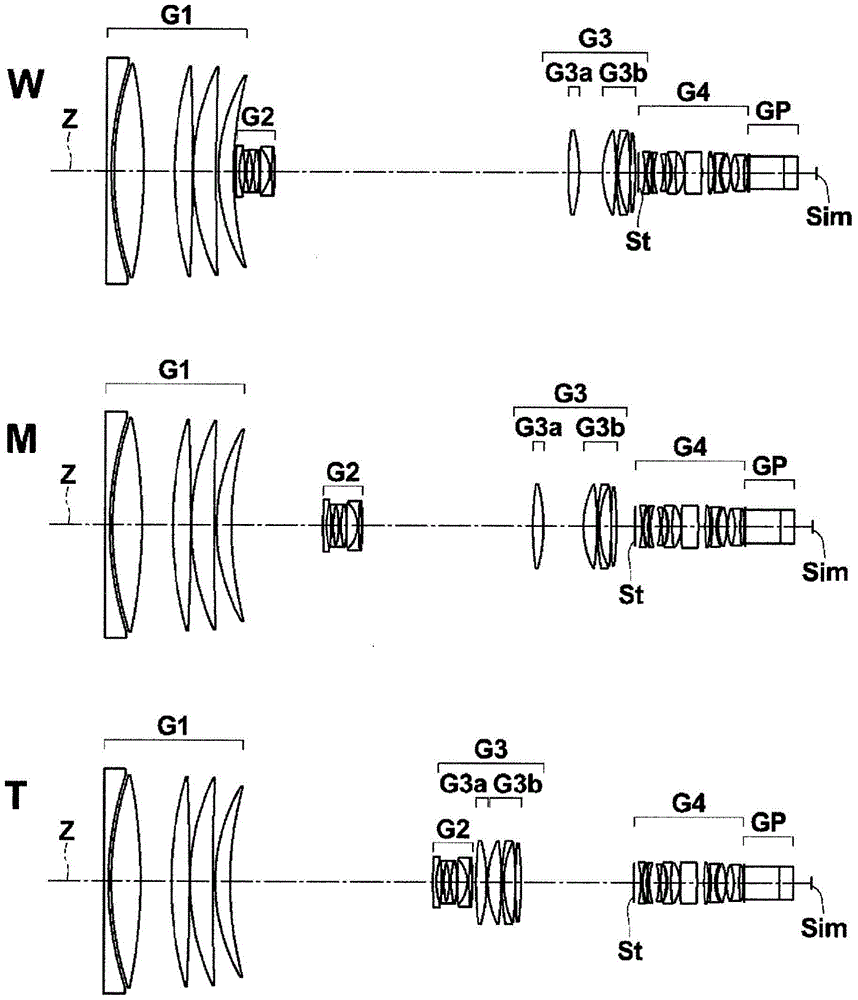
[0112] Figure 4 A lens configuration diagram of the zoom lens of Example 2 is shown in . The schematic configuration of the zoom lens of the second embodiment is substantially the same as that of the zoom lens of the first embodiment described above. Table 4, Table 5, and Table 6 show basic lens data, aspheric coefficients, various elements, and variable surface intervals of the zoom lens of Example 2, respectively. Figure 10 (A)~ Figure 10 Each aberration diagram of the zoom lens of Example 2 is shown in (L).

[0113] 【Table 4】

[0114]

[0115]

[0116] 【table 5】

[0117]

[0118]

[0119] 【Table 6】

[0120]

Embodiment 3

[0122] Figure 5 A lens configuration diagram of the zoom lens of Example 3 is shown in . The schematic configuration of the zoom lens of Example 3 is substantially the same as that of the zoom lens of Example 1 above, but differs in that the fourth lens group G4 is composed of 15 lenses. Table 7, Table 8, and Table 9 show basic lens data, aspheric coefficients, various elements, and variable surface intervals of the zoom lens of Example 3, respectively. Figure 11 (A)~ Figure 11 Each aberration diagram of the zoom lens of Example 3 is shown in (L).

[0123] 【Table 7】

[0124]

[0125]

[0126] 【Table 8】

[0127]

[0128]

[0129] 【Table 9】

[0130]


PUM


Abstract

The present invention provides a zoom lens that achieves high magnification, wide angle, and high performance in the entire zoom range at the same time, and an imaging device including the zoom lens. From the object side, the zoom lens consists of: the positive first lens group (G1) that is fixed when changing magnification, the negative second lens group (G2) that moves when changing magnification, and the lens group that moves when changing magnification. The positive third lens group (G3) that corrects the fluctuation of the image plane, and the positive fourth lens group (G4) that is fixed when changing magnification and has a diaphragm on the most object side. The second lens group (G2) has two or more positive lenses and one or more negative lenses. When the Abbe number and the partial dispersion ratio of one positive lens of the second lens group (G2) are vp and Pp respectively, the conditional expression (1): 75.00<vp, the conditional expression (2): 0.520<Pp< 0.550.

Description

technical field [0001] The present invention relates to a zoom lens and an imaging device, and more specifically, to a zoom lens suitable for mounting on a television camera, a video camera, and the like, and an imaging device including the zoom lens. Background technique [0002] As zoom lenses mounted on television cameras, video cameras, etc., for example, a four-group type zoom lens described in Patent Document 1 below is known. It is composed of, in order from the object side, a first lens group that is fixed during magnification change, a second lens group that has a magnification change function, a third lens group that has a correction function for image plane fluctuations accompanying magnification change, The 4th lens group is fixed when zooming. [0003] In addition, in order to achieve high performance, although it is a 4-group type, a type in which the second lens group or the third lens group is divided has also been proposed. For example, Patent Document 2 b...

Claims


Application Information

Patent Timeline
Patent Type & Authority Patents(China)
IPC IPC(8): G02B15/20G02B13/18H04N5/232
CPCG02B15/173G02B15/144113
Inventor 青井敏浩池田伸吉
Owner FUJIFILM CORP
Why Eureka
Try Eureka