
A control method of line anti-vibration system with adjustable resonant frequency

A technology of resonant frequency and control method, applied in the direction of mechanical vibration attenuation devices, etc., can solve the problems of high resonant frequency of overhead transmission lines and inability to match the vibration frequency of most transmission lines

Active Publication Date: 2017-03-29
STATE GRID CORP OF CHINA +2
View PDF4 Cites 0 Cited by
  • Summary
  • Abstract
  • Description
  • Claims
  • Application Information

AI Technical Summary

Problems solved by technology

[0004] The purpose of the present invention is to solve the problem that the self-resonant frequency of the existing vibration isolator can only match the vibration frequency of several transmission lines, but cannot match the vibration frequency of most transmission lines, resulting in a high resonance frequency of overhead transmission lines, and proposes A control method of line anti-vibration system with adjustable resonant frequency

Method used


Image

  • A control method of line anti-vibration system with adjustable resonant frequency
  • A control method of line anti-vibration system with adjustable resonant frequency
  • A control method of line anti-vibration system with adjustable resonant frequency

Examples


specific Embodiment approach 1

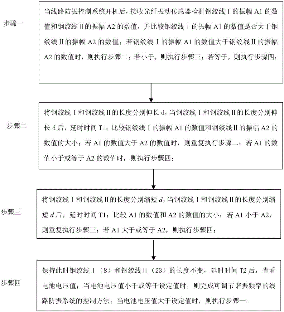
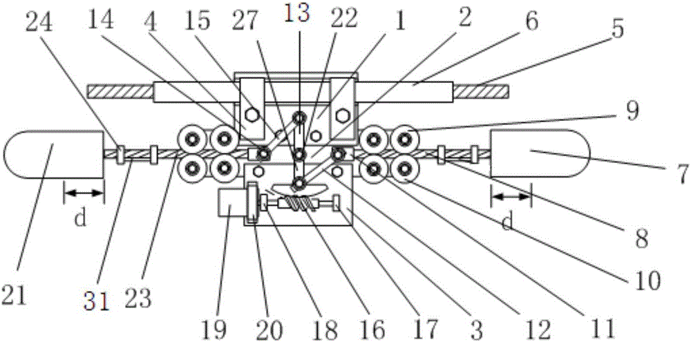
[0026] Specific implementation mode one: combine figure 1 with figure 2 To illustrate this embodiment, a control method of a line anti-vibration system with adjustable resonance frequency is specifically carried out according to the following steps:

[0027] The line anti-vibration system with adjustable resonance frequency includes a vibration isolator with adjustable resonance frequency and a control assembly, the control assembly is electrically connected with the vibration isolator with adjustable resonance frequency, and the vibration isolator with adjustable resonance frequency includes a line Wire clamp part 1, middle support plate 2, lower support plate 3, wire clamp buckle 4, overhead wire 5, wire protection sleeve 6, rotating rod 13, central shaft 22, screw rod 16 and stepping motor 19, line clamp part 1 The wire clip 4 is pressed onto the protective wire cover 6 set on the overhead line 5, the middle pallet 2 and the lower pallet 3 are connected with the wire clam...

specific Embodiment approach 2

[0050] Embodiment 2: The difference between this embodiment and Embodiment 1 is that the line anti-vibration control system in the step 1 is also equipped with a system reset module. When the system reset module is started, the steel strand I8 and the steel strand II23 The elongation distance between them is equal to 50%-90% of the total length of steel strand I8 or steel strand II23.

[0051] Other steps and parameters are the same as those in Embodiment 1.

specific Embodiment approach 3

[0052] Embodiment 3: The difference between this embodiment and Embodiment 1 or 2 is: in the step 1, the optical fiber vibration sensor 31 detects the value of the amplitude A1 of the steel strand I8 and the value of the amplitude A2 of the steel strand II23 for:

[0053] The value of the amplitude A1 of the detected steel strand I8 and the value of the amplitude A2 of the steel strand II23 are respectively averaged,

[0054]

[0055]

[0056] in:

[0057]

[0058] k is a natural number;

[0059] A1(i) is the sampling value of the amplitude of the steel strand I8 detected by the fiber optic vibration sensor 31 for the i time, the sampling interval is T1 / n, and i is a positive integer;

[0060] A2(i) is the sampling value of the amplitude of the steel strand II 23 detected by the optical fiber vibration sensor 31 for the ith time, the sampling interval is T1 / n, and i is a positive integer.

[0061] Other steps and parameters are the same as those in Embodiment 1 or ...


PUM


Abstract

The invention discloses a control method for a circuit anti-vibration system capable of adjusting resonant frequency, relates to the control method for circuit anti-vibration systems and aims at solving the problems that the self-resonant frequency of an existing antivibrator can only be matched with the vibrational frequencies of a few electric transmission lines and can not be matched with the vibrational frequencies of most electric transmission lines, and the defect lead to the fact that the resonant frequency of overhead transmission lines is high. According to the technical scheme, the method comprises the following steps including the first step that when the circuit anti-vibration system is turned on, A1 and A2 are received, if A1 is larger than A2, then the second step is executed; if A1 is smaller than A2, then the third step is executed; if A1 is equal to A2, then the fourth step is executed; the second step that the lengths of a first steel strand and a second steel strand are each prolonged by d; if A1 is larger than A2, then the second step is executed; if A1 is smaller than or equal to A2, then the fourth step is executed; the third step that the ds are shortened respectively; if A1 is smaller than A2, then the third step is executed; if A1 is larger than or equal to A2, then the fourth step is executed; the fourth step that the voltage value is checked, and when the voltage value is smaller than or equal to a set value, then the control method is finished. The control method for the circuit anti-vibration system capable of adjusting the resonant frequency is suitable for being used in the power transmission field.

Description

technical field [0001] The invention relates to a control method of a line anti-vibration system. Background technique [0002] Breeze vibrations of transmission lines and wind vibrations of transmission towers often cause extremely harmful faults such as broken strands and broken wires of transmission lines, node connection damage of poles and towers, and many times caused serious large-scale power outages. There are three forms of wind-induced conductor vibration of overhead transmission lines: breeze vibration, sub-gap vibration and galloping, among which the breeze vibration of conductors occurs most frequently and has the greatest impact. The breeze vibration of the wire is due to the periodic "Karman vortex" excitation behind the wire when the wind blows through the wire vertically, which generates a force on the wire perpendicular to the wire and the wind direction, causing the wire to generate breeze vibration. If the line breeze vibration is not properly controlled...

Claims


Application Information

Patent Timeline
Patent Type & Authority Patents(China)
IPC IPC(8): H02G7/14
CPCH02G7/14
Inventor 李童刘洋朱学成于春来王瑞发孙福军盛玉和张德文柳贡强张洪达张国力
Owner STATE GRID CORP OF CHINA
Learn More