
Method for conducting magnetic resonance advanced detection through rotation of loop antenna

A loop antenna and advanced detection technology, applied in the field of advanced detection, can solve the problem of being unable to distinguish which space the water-bearing body comes from, and achieve the effect of improving accuracy

Active Publication Date: 2015-07-08
JILIN UNIV
View PDF7 Cites 13 Cited by
  • Summary
  • Abstract
  • Description
  • Claims
  • Application Information

AI Technical Summary

Problems solved by technology

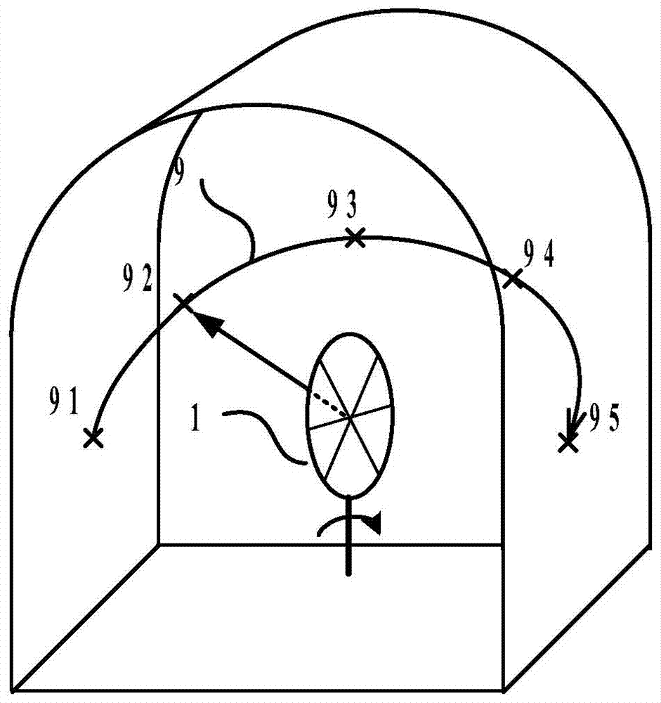
[0008] The technical problem to be solved by the present invention is to provide a method for magnetic resonance advanced detection by rotating the loop antenna, which aims to use the rotating loop antenna for multi-angle detection and two-dimensional imaging, and can effectively determine the specific location of the water body. It also effectively solves the problem that it is impossible to distinguish which space the water body comes from due to the full-space radiation of the loop antenna

Method used


Image

  • Method for conducting magnetic resonance advanced detection through rotation of loop antenna
  • Method for conducting magnetic resonance advanced detection through rotation of loop antenna
  • Method for conducting magnetic resonance advanced detection through rotation of loop antenna

Examples


Embodiment Construction

[0042] In order to make the object, technical solution and advantages of the present invention clearer, the present invention will be further described in detail below in conjunction with the accompanying drawings and embodiments. It should be understood that the specific embodiments described here are only used to explain the present invention, not to limit the present invention.

[0043] see figure 1 , a schematic structural diagram of the equipment used in the method of the present invention, the equipment includes a loop antenna 1, a horizontal rotation axis 2, an antenna support 3, a vertical rotation axis 4, an antenna base 5 and a magnetic resonance detection instrument 6, and the antenna support 3 is a semi-circular structure, The symmetrical point of the semicircle is connected to the antenna base 5 through the rotation of the vertical rotation axis 4. The width of both ends of the semicircle of the antenna support 3 is matched with the loop antenna 1, and the loop an...


PUM


Abstract

The invention relates to a method for conducting magnetic resonance advanced detection through rotation of a loop antenna. According to the method for conducting magnetic resonance advanced detection through rotation of the loop antenna, the loop antenna is fixed to a rotary support, measurement based on vertical rotation and measurement based on horizontal rotation are adopted, in a tunnel or a mine, a water-contained body in front of a tunnel face, a water-contained body of a roof, a water-contained body of a base plate, a water-contained body of the left side wall and a water-contained body of the right side wall are detected, hydrological parameter inversion is conducted on an obtained magnetic resonance signal, and thus a two-dimensional water content sector diagram is obtained. According to the method for conducting magnetic resonance advanced detection through rotation of the loop antenna, a one-dimensional magnetic resonance detection method is expanded into a two-dimensional magnetic resonance imaging method; compared with one-dimensional detection according to which only whether a water-contained body exists right in front can be judged, the method has the advantages that the rotary loop antenna is used for multi-angle detection and two-dimensional imaging, and the specific positions, the scales and the water contents of the water-contained bodies can be accurately judged; in addition, the problem that the space which the water-contained body is from can not be determined due to totals-space radiation of the antenna is effectively solved. By the adoption of the method, magnetic resonance detection precision is improved, the spatial distribution of the water-contained bodies nearby the tunnel face can be reflected more accurately, and life and property losses caused by the geological disasters such as water inrush and water burst during tunnel or mine construction are reduced.

Description

technical field [0001] The invention belongs to the field of advanced detection in the field of geophysical exploration, in particular to a method for magnetic resonance advanced detection by using loop antenna rotation. Background technique [0002] Due to complex geological conditions, geological disasters such as water inrush and gushing occur frequently in underground excavation projects such as tunnels and mines, which have brought huge casualties and economic losses. The advanced detection of water-bearing bodies in front of tunnels and mine shafts has become an important research topic, which is of great significance for formulating water inrush prevention measures and evaluating construction safety. [0003] Magnetic Resonance Sounding (MRS for short) is a direct geophysical prospecting method. Compared with traditional geophysical indirect detection methods, MRS has the advantages of high resolution, high efficiency, rich information and unique interpretation, and ...

Claims


Application Information

Patent Timeline
Patent Type & Authority Applications(China)
IPC IPC(8): G01V3/14
Inventor 蒋川东林君段清明林婷婷易晓峰范铁刘骏妍于雷陈武强冷舒喆
Owner JILIN UNIV
Learn More