Compound type heat pump unit and concentrated heating system
A heat pump unit and composite technology, which are applied in hot water central heating systems, heating systems, household heating and other directions, can solve the problems of insufficient primary water inlet lift and increased lift, and achieve a reduction in primary water pressure drop, The effect of increasing the flow velocity in the pipe and reducing the primary water pressure drop
- Summary
- Abstract
- Description
- Claims
- Application Information
AI Technical Summary
Problems solved by technology
Method used
Image

Examples
no. 1 example
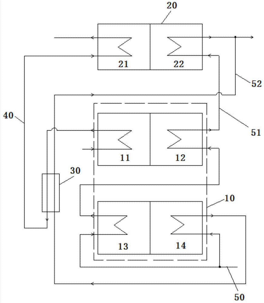
[0050] figure 1 It is a schematic diagram of the principle of the composite heat pump unit according to the first embodiment of the present invention.
[0051] Such as figure 1 As shown, the composite heat pump unit of the first embodiment includes an absorption heat pump 10 , a compression refrigerator 20 , a heat exchanger 30 , a primary side pipeline 40 and a secondary side pipeline 50 .
[0052] The absorption heat pump 10 includes a generator 11 , an absorption heat pump condenser 12 , an absorber 13 and an absorption heat pump evaporator 14 .
[0053] The compression refrigerator 20 includes a compression refrigerator evaporator 21 and a compression refrigerator condenser 22 .
[0054] The primary side pipeline 40 is connected in series with the generator 11, heat exchanger 30 and compression refrigerator evaporator 21 along the water flow direction, and the primary side pipeline 40 is only connected with the generator 11 and the absorption heat pump evaporator 14. De...
no. 2 example
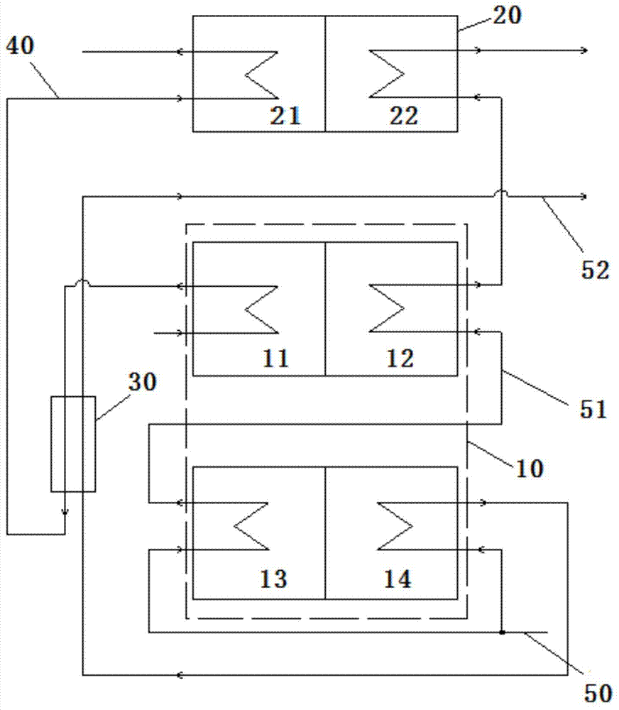
[0065] figure 2 It is a schematic diagram of the principle of the composite heat pump unit according to the second embodiment of the present invention.
[0066] Such as figure 2 As shown, the difference between the second embodiment and the first embodiment is that the second end of the first branch pipe 51 located at the secondary water outlet end of the condenser 22 of the compression refrigerating machine and the second end of the first branch pipe 51 located at the secondary water outlet end of the heat exchanger 30 The second ends of the second branch pipes 52 respectively output secondary water outlets. Therefore, the secondary water outlet at the second end of the second branch pipe 52 and the secondary water outlet at the second end of the first branch pipe 51 are respectively used to provide heat for the user.
[0067] The flow process of primary water and secondary water in the second embodiment will be described below.
[0068] The primary water first enters th...
no. 3 example
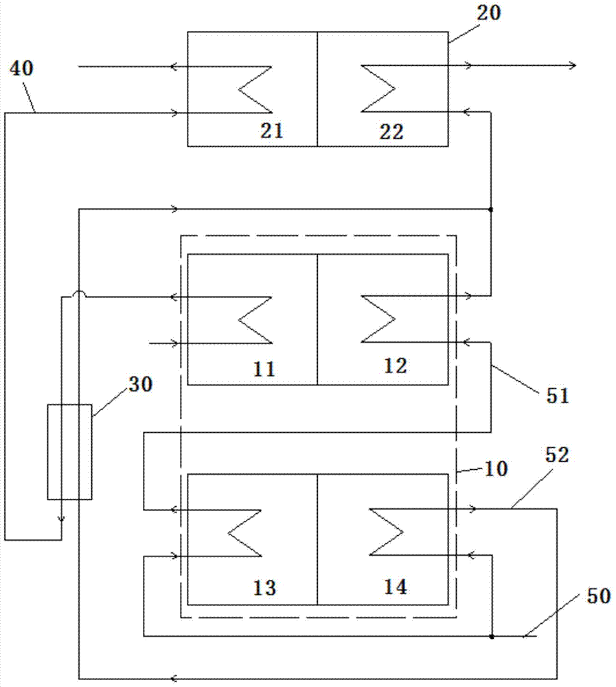
[0073] image 3 It is a schematic diagram of the principle of the composite heat pump unit according to the third embodiment of the present invention.
[0074] Such as image 3 As shown, the composite heat pump unit of the third embodiment includes an absorption heat pump 10 , a compression refrigerator 20 , a heat exchanger 30 , a primary side pipeline 40 and a secondary side pipeline 50 .
[0075] The absorption heat pump 10 includes a generator 11 , an absorption heat pump condenser 12 , an absorber 13 and an absorption heat pump evaporator 14 .
[0076] The compression refrigerator 20 includes a compression refrigerator evaporator 21 and a compression refrigerator condenser 22 .
[0077] The primary side pipeline 40 is connected in series with the generator 11, heat exchanger 30 and compression refrigerator evaporator 21 along the water flow direction, and the primary side pipeline 40 is only connected with the generator 11 and the absorption heat pump evaporator 14. De...
PUM
 Abstract
Description
Claims
Application Information
 - Generate Ideas
- Intellectual Property
- Life Sciences
- Materials
- Tech Scout
- Unparalleled Data Quality
- Higher Quality Content
- 60% Fewer Hallucinations
Browse by: Latest US Patents, China's latest patents, Technical Efficacy Thesaurus, Application Domain, Technology Topic, Popular Technical Reports.
© 2025 PatSnap. All rights reserved.Legal|Privacy policy|Modern Slavery Act Transparency Statement|Sitemap|About US| Contact US: help@patsnap.com