
Supersonic combustion chamber cavity ignition device and scramjet engine

A technology of supersonic combustion chamber and ignition device, which is applied in the direction of combustion chamber, continuous combustion chamber, combustion method, etc., can solve the problems of reduced ignition success rate, direct flameout, fuel enrichment, etc., so as to reduce enrichment and increase success. rate effect

Active Publication Date: 2015-07-08
NAT UNIV OF DEFENSE TECH
View PDF7 Cites 21 Cited by
  • Summary
  • Abstract
  • Description
  • Claims
  • Application Information

AI Technical Summary

Problems solved by technology

Although this supersonic combustion chamber concave cavity ignition device can increase the probability of successful ignition to a certain extent, due to the particularity of the concave cavity structure, when the fuel injection hole continuously injects fuel, the fuel flowing back into the concave cavity is very difficult. The phenomenon of enrichment is prone to occur, which in turn affects the mixing ratio of fuel and air, resulting in a decrease in the success rate of ignition, or even ignition failure, or direct flameout, etc.

Method used


Image

  • Supersonic combustion chamber cavity ignition device and scramjet engine
  • Supersonic combustion chamber cavity ignition device and scramjet engine
  • Supersonic combustion chamber cavity ignition device and scramjet engine

Examples


Embodiment Construction

[0028] In order to enable those skilled in the art to better understand the technical solutions in the application, the following will clearly and completely describe the technical solutions in the embodiments of the application with reference to the drawings in the embodiments of the application. Obviously, the described The embodiments are only a part of the embodiments of the present application, rather than all the embodiments.

[0029] Based on the embodiments in this application, all other embodiments obtained by those of ordinary skill in the art without creative work should fall within the protection scope of this application.

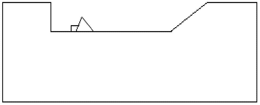
[0030] As attached figure 2 , Attached image 3 And Figure 4 Shown, attached figure 2 , Attached image 3 And Figure 4 A specific embodiment of a cavity ignition device for a supersonic combustion chamber is provided. As shown in the drawings, the cavity ignition device for a supersonic combustion chamber includes a mounting base 1, a fuel inject...


PUM


Abstract

The invention discloses a supersonic combustion chamber cavity ignition device and a scramjet engine. The supersonic combustion chamber cavity ignition device comprises an installation base. Fuel spray holes are formed in the upstream portion of the installation base. A cavity is formed in the downstream portion of the installation base. The fuel spray holes and the cavity are formed in the same plane of the installation base. An ignition plug is arranged on the bottom surface of the cavity. A stop piece is arranged in the downstream direction of the ignition plug. The stop piece comprises a left stop piece body and a right stop piece body which have the same triangular shape. One edge of the left stop piece body is connected with the edge, with the same length, of the right stop piece body, and the other group of adjacent edges of the left stop piece body and the right stop piece body are fixed to the bottom face of the cavity. The included angle a between the left stop piece body and the right stop piece body in the direction towards the ignition plug is smaller than 180 degrees. According to the supersonic combustion chamber cavity ignition device, fuel is lifted through the stop piece, the probability that the fuel is accumulated at the position of the ignition plug is effectively reduced, it is guaranteed that the fuel and air have an appropriate mixing ratio, and the success rate of ignition is improved.

Description

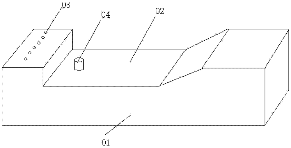
Technical field [0001] The invention relates to a supersonic combustion chamber, and more particularly, to a cavity ignition device of a supersonic combustion chamber and a super-combustion ramjet. Background technique [0002] In the supersonic combustion chamber, because the fuel is flowing at a high speed, it is usually difficult to ignite, mix and burn the fuel. In the prior art, in order to make the fuel ignite more smoothly, a cavity is usually set in the ignition area. In this way, the supersonic airflow When flowing through the cavity, a recirculation zone is formed in the cavity, which can keep the flame in it all the time and continue to ignite the fuel delivered upstream as a new fire source. Attached figure 1 A structural schematic diagram of a cavity ignition device for a supersonic combustion chamber in the prior art is provided. figure 1 The cavity ignition device of the supersonic combustion chamber includes a mounting seat 01, a cavity 02 is arranged in the mount...

Claims


Application Information

Patent Timeline
Patent Type & Authority Applications(China)
IPC IPC(8): F23R3/28
Inventor 蔡尊孙明波王振国
Owner NAT UNIV OF DEFENSE TECH
Learn More