
Combined silencing, sound-insulating and vibration-isolating device of centrifugal fan

A centrifugal fan and composite technology, applied in parts of pumping devices for elastic fluids, mechanical equipment, non-variable pumps, etc., can solve environmental noise pollution in industrial enterprises, affect the service life of motors and circuit safety, Unable to reduce the noise of the metal shell of the fan, etc., to achieve the effect of improving the noise reduction

Inactive Publication Date: 2015-07-08
ANHUI WEIWEI RUBBER PARTS GRP
View PDF14 Cites 4 Cited by
  • Summary
  • Abstract
  • Description
  • Claims
  • Application Information

AI Technical Summary

Problems solved by technology

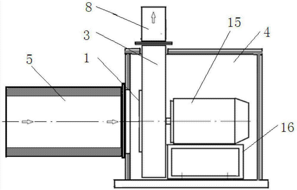
[0002] The vibration and noise produced by the centrifugal fan is one of the main reasons for the environmental noise pollution of industrial enterprises. There are two main measures to reduce the noise of the fan (see figure 2 ): one is to install the muffler 5 directly at the fan air inlet 1 of the fan 3, this method is only effective for reducing the intake noise of the fan, but cannot reduce the noise radiated by the metal casing of the fan; the other is to install the muffler 5 on the fan 3 The sound insulation cover 4 is placed on the outer cover of the sound insulation cover 4, and the muffler 5 is installed at the external air inlet of the sound insulation cover 4. Although this method reduces the noise emitted by the fan casing, it cannot control the sound transmission of the fan through the structure of the bottom mounting frame. , and because the motor is also covered in the sound insulation cover, the heat generated by the motor cannot be dissipated, which affects the service life of the motor and the safety of the circuit

Method used


Image

  • Combined silencing, sound-insulating and vibration-isolating device of centrifugal fan
  • Combined silencing, sound-insulating and vibration-isolating device of centrifugal fan

Examples


Embodiment Construction

[0019] The embodiments of the present invention will be described in detail below with reference to the accompanying drawings, but the present invention can be implemented in many different ways defined and covered by the claims.

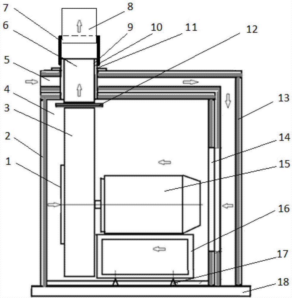
[0020] Such as figure 1 As shown, the sound-insulation and vibration-isolation composite device of the centrifugal fan includes a muffler 5, a sound-insulation cover 4 and a vibration isolator 17. Outside the air outlet 14, other surfaces are all sealed to each other. The air inlet of the muffler is located on one side of the sound insulation cover 4, and the muffler air outlet 14 is located on the other side of the sound insulation cover 4. The muffler parts on the two sides Constitute a muffler elbow, form an L-shaped muffler channel, and increase the muffler capacity.

[0021] The exhaust hole of the sound insulation cover is composed of an inner exhaust connecting pipe 9 and an outer exhaust connecting pipe 10. The inner exhaust connecting pip...


PUM


Abstract

The invention discloses a combined silencing, sound-insulating and vibration-isolating device of a centrifugal fan. The combined silencing, sound-insulating and vibration-isolating device of the centrifugal fan comprises a silencer, an acoustic shield and vibration isolators, the silencer is integrated with the acoustic shield, silencer parts on two lateral surfaces form a silencing elbow, and an L-shaped silencing passage is formed to improve the silencing capacity; a fan, a motor and a bracket are arranged on a heavy concrete pedestal through a plurality of vibration isolators, and the mass centers of the fan, motor and bracket pass through the centers of the vibration isolator planes so as to prevent the fan shaking. The combined silencing, sound-insulating and vibration-isolating device of the centrifugal fan is simple in structure, the silencer is integrated with the acoustic shield, the silencer is L-shaped, the amplitude of the silencing and sound-insulating device is reduced, and the silencing capacity is improved; the device is arranged on the heavy concrete pedestal through the vibration isolators, and the mass center of the whole body passes through the centers of the vibration isolator planes so as to prevent the fan shaking.

Description

technical field [0001] The invention belongs to the field of fan noise control, and in particular relates to a sound-absorbing, sound-insulating, and vibration-isolating composite device for a centrifugal fan. Background technique [0002] The vibration and noise produced by the centrifugal fan is one of the main reasons for the environmental noise pollution of industrial enterprises. There are two main measures to reduce the noise of the fan (see figure 2 ): one is to install the muffler 5 directly at the fan air inlet 1 of the fan 3, this method is only effective for reducing the intake noise of the fan, but cannot reduce the noise radiated by the metal casing of the fan; the other is to install the muffler 5 on the fan 3 The sound insulation cover 4 is placed on the outer cover of the sound insulation cover 4, and the muffler 5 is installed at the external air inlet of the sound insulation cover 4. Although this method reduces the noise emitted by the fan casing, it canno...

Claims


Application Information

Patent Timeline
Patent Type & Authority Applications(China)
IPC IPC(8): F04D29/66F04D29/58
Inventor 李俊李志远李斌商李徐兵
Owner ANHUI WEIWEI RUBBER PARTS GRP
Learn More