
Die cutting device and method

A die-cutting and one-die-cutting technology, applied in metal processing and other directions, can solve the problems of high manufacturing cost and low degree of automation

Active Publication Date: 2015-07-08
ANHUI JINGZHUO OPTICAL DISPLAY TECH CO LTD
View PDF8 Cites 9 Cited by
  • Summary
  • Abstract
  • Description
  • Claims
  • Application Information

AI Technical Summary

Problems solved by technology

[0005] In the traditional film die-cutting process, in order to prevent the film from being scratched by mechanical material distribution, a large amount of manpower is required to separate the cutting material and waste material while the cutting machine is slicing. The degree of automation in production is not high, resulting in manufacturing costs. higher

Method used


Image

  • Die cutting device and method
  • Die cutting device and method
  • Die cutting device and method

Examples


Embodiment Construction

[0031] Typical embodiments embodying the features and advantages of the present invention will be described in detail in the following description. It should be understood that the invention is capable of various changes in different embodiments without departing from the scope of the invention, and that the description and illustrations therein are illustrative in nature and not limiting. this invention.

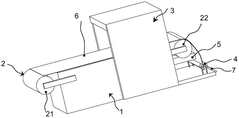
[0032] Such as figure 1 As shown, the present invention provides a die-cutting device, which includes a frame 1 , a conveying mechanism 2 , a die-cutting mechanism 3 , a stripping traction mechanism 4 and an ejecting mechanism 5 .

[0033] The conveying mechanism 2 can have a feeding part 21 and a discharging part 22 installed on the frame 1. The conveying mechanism 2 can convey a substrate 6 to be die-cut through the die-cutting mechanism 3. The feeding part 21 and the discharging part 22 are respectively located at Both sides of the die-cutting mechanism 3; such as fig...


PUM


Abstract

The invention provides a die cutting device and a method. The device comprises a frame, a conveying mechanism and a die cutting mechanism, wherein the dir cutting mechanism has a feed part and a discharge part mounted on the frame; the conveying mechanism conveys a basal material to be cut to pass through the die cutting mechanism; and the feed part and the discharge part are respectively positioned at the two sides of the die cutting mechanism. The device is characterized by further comprising a mold release towing mechanism and an ejection mechanism; the mold release towing mechanism is positioned below the discharge part, and downwards tows the cut basal material from the discharge part; the ejection device is arranged between the discharge part and the mold release towing mechanism, and has a projection; and the projection can be corresponding to the cut basal material at the inner side, and is outwards projected on the cut basal material. After an automatic film die cutting device is applied, the automatic material separation after the die cutting and the continuous operation can be realized, one person is only needed to operate, the working efficiency is improved, and the labor is saved.

Description

technical field [0001] The invention relates to a die-cutting device, in particular to an automatic die-cutting device and method for touch screen production. Background technique [0002] With the development of electronic technology, in the early 1990s, a new human-computer interaction technology - touch screen technology emerged. Using this technology, the user can operate the host by lightly touching the icons or text on the display screen of the electronic product with his fingers, which eliminates keyboard and mouse operations and makes human-computer interaction more straightforward. Therefore, touch screen technology has become the most convenient input device for man-machine communication. [0003] A touch screen system generally includes two parts: a touch screen controller (card) and a touch detection device. The main function of the touch screen controller (card) is to receive touch information from the touch point detection device, convert it into contact coor...

Claims


Application Information

Patent Timeline
Patent Type & Authority Applications(China)
IPC IPC(8): B26D7/18B26D7/06
Inventor 金小龙唐彬李赟
Owner ANHUI JINGZHUO OPTICAL DISPLAY TECH CO LTD
Learn More