Welding stress frame used for light enclosure wall structure of vessel

A welding pressure and surrounding wall technology, applied in welding equipment, auxiliary welding equipment, welding/cutting auxiliary equipment, etc., can solve the problems of long turnover period, large welding workload, danger of lifting and transporting weights, etc., and reduce welding construction. Cost, stable welding performance, and the effect of ensuring welding quality

Active Publication Date: 2015-07-08
CSSC HUANGPU WENCHONG SHIPBUILDING COMPANY
View PDF6 Cites 1 Cited by
  • Summary
  • Abstract
  • Description
  • Claims
  • Application Information

AI Technical Summary

Problems solved by technology

[0003] After the current light wall structure is assembled, there are two construction forms for frame welding: one is welding in a free state, laying the light wall on the platform, and welding it with manual or automatic corner welding machines. This construction method The disadvantage is that the welding workload is large, especially after welding, the plate is prone to large wave deformation, which must be eliminated by pyrotechnic correction, which increases the difficulty of construction; the other is to use a crane to transport The plate-shaped iron presses both sides of the structure to compress the plates, and uses a semi-automatic or automatic fillet welding machine to weld the wall structure to reduce the welding deformation of the light wall. The disadvantage of this method is that it requires a large number of people. , Occupies a large site, long turnover period, there is a greater risk of lifting weighted iron, the welding efficiency is low, and the requirements for the flatness of the site are high

Method used


Image

  • Welding stress frame used for light enclosure wall structure of vessel
  • Welding stress frame used for light enclosure wall structure of vessel
  • Welding stress frame used for light enclosure wall structure of vessel

Examples


Embodiment 1

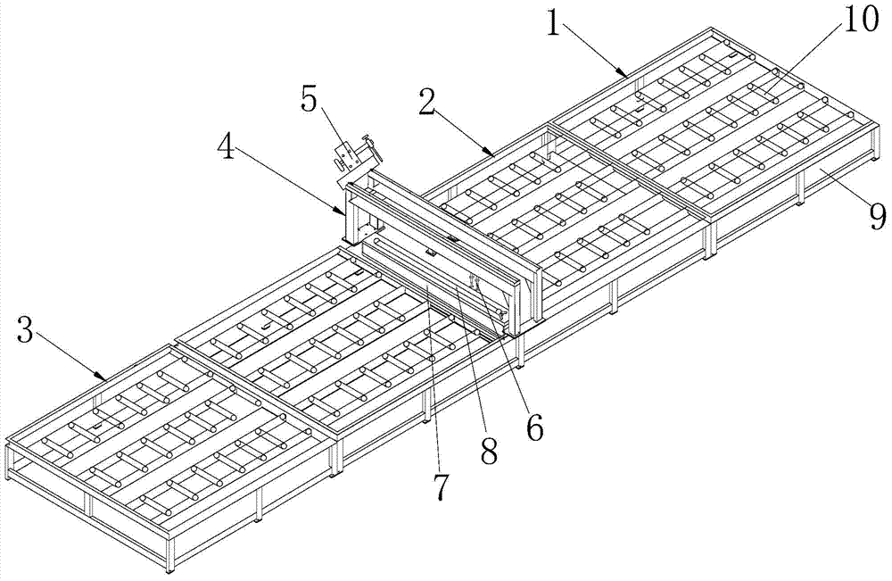
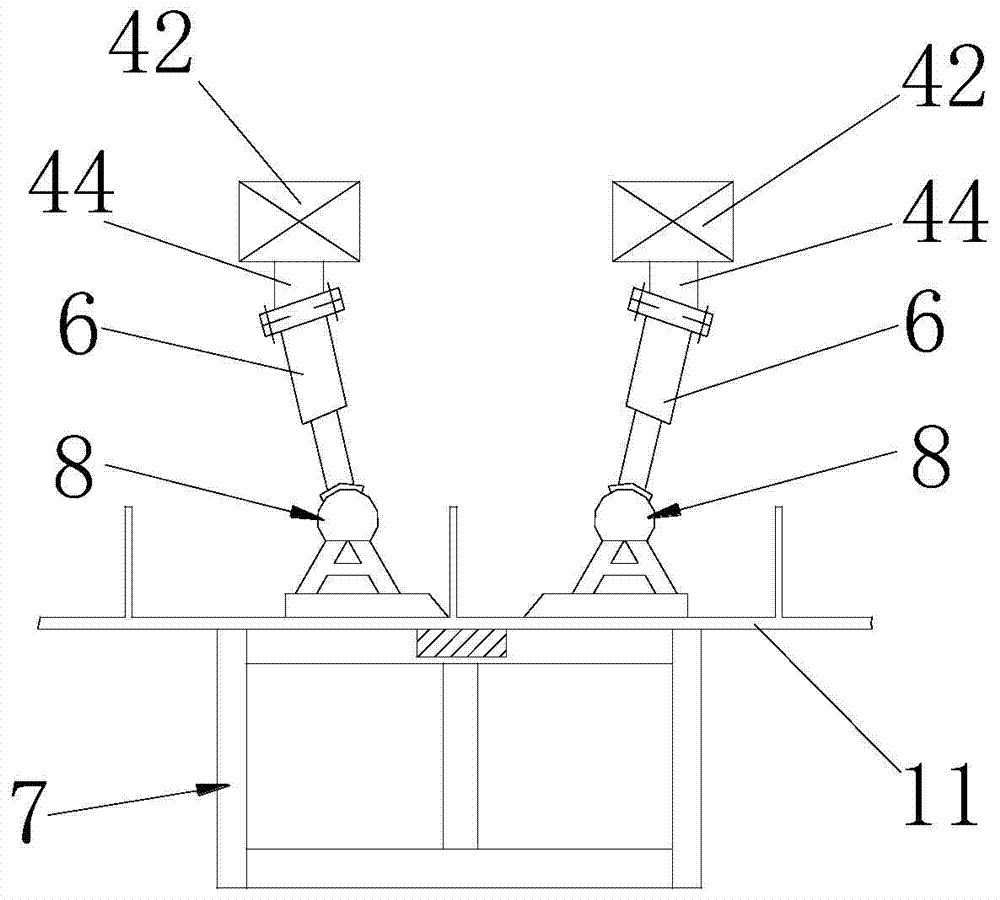
[0027] Such as figure 1 As shown, the welding pressure frame of the light enclosure structure of the ship in this embodiment includes a conveying system for transporting the light enclosure structure 11 of the ship and a fixed welding for fixing and welding the light enclosure structure 11 of the ship. system, the fixed welding system is arranged across the upper part of the conveying system, the fixed welding system includes a welding gantry 4 arranged across the conveying system, a welding trolley 5 is arranged above the beam of the welding gantry 4, The bottom of the beam is provided with a compression hydraulic cylinder 6 for compressing the ship's light enclosure structure 11 from above, and also includes a support system for compressing the ship's light enclosure structure 11 from below. The supporting platform 7 on the conveying system and the platen structure 8 arranged on the supporting platform 7 .

[0028] The welded pressure frame of the light enclosure wall struc...


PUM


Abstract

The invention relates to a welding stress frame used for a light enclosure wall structure of a vessel. The welding stress frame comprises a conveying structure used for conveying the light enclosure wall structure and a fixed welding system used for fixing the light enclosure wall structure and conducting welding operation, the fixed welding system comprises a welding portal frame which is arranged on the conveying system in a crossed mode, a welding tractor is arranged on a cross beam of the welding portal frame, a compressing hydraulic cylinder used for compressing the light enclosure wall structure from above is arranged below the cross beam, the welding stress frame further comprises a supporting system used for compressing the light enclosure wall structure from below, the light enclosure wall structure is compressed and fixed through the compressing hydraulic cylinder from above and the supporting system from below respectively, the deformation of the light enclosure wall structure in the welding process can be effectively controlled without hoisting a pressing plate, the welding performance is stable, the welding quality is guaranteed effectively, the safety performance is high, the automatic welding for welding joints can be achieved through program control, the welding efficiency is greatly enhanced, it is facilitated to shorten the assemble welding cycle of a wallboard, and the construction cost of welding is reduced.

Description

technical field [0001] The invention relates to the technical field of ship tooling, in particular to a welded pressure frame for a ship's light surrounding wall structure. Background technique [0002] There are many internal compartments in the structure of military ships. In order to reduce the dead weight of the ship and increase the speed of the ship, the structure between the internal compartments generally adopts a light-weight wall panel structure. Lightweight wall panels are generally composed of wall panels and stiffener structures through welding. Due to the light structure, it is prone to large deformation during the welding process. Therefore, the control of welding deformation is an important aspect to ensure the quality of ship construction. . [0003] After the current light wall structure is assembled, there are two construction forms for frame welding: one is welding in a free state, laying the light wall on the platform, and welding it with manual or auto...

Claims


Application Information

Patent Timeline
Patent Type & Authority Applications(China)
IPC IPC(8): B23K37/00B23K37/04B23K37/02
CPCB23K37/00B23K37/0229B23K37/0426
Inventor 陈红亮何源
Owner CSSC HUANGPU WENCHONG SHIPBUILDING COMPANY
Why Eureka
Try Eureka