
Buffer device for impact device, impact device, rock drill and method of buffering in a rock drill

A technology of buffer device and impact device is applied in drilling equipment and method, driving device of rotary combined drilling, earthwork drilling and other directions to achieve the effect of energy saving

Active Publication Date: 2016-09-21
EPIROC ROCK DRILLS AB
View PDF8 Cites 0 Cited by
  • Summary
  • Abstract
  • Description
  • Claims
  • Application Information

AI Technical Summary

Problems solved by technology

The damping chamber in which the damping piston is arranged is connected to the accumulator and previously known representative dampers of this type are used as hydraulic springs, wherein there is practically no worthwhile provision for achieving a real damping of the reflections emanating from drilling. The reception or consumption of energy and thus produce undesired oscillating system

Method used


Image

  • Buffer device for impact device, impact device, rock drill and method of buffering in a rock drill
  • Buffer device for impact device, impact device, rock drill and method of buffering in a rock drill
  • Buffer device for impact device, impact device, rock drill and method of buffering in a rock drill

Examples


Embodiment Construction

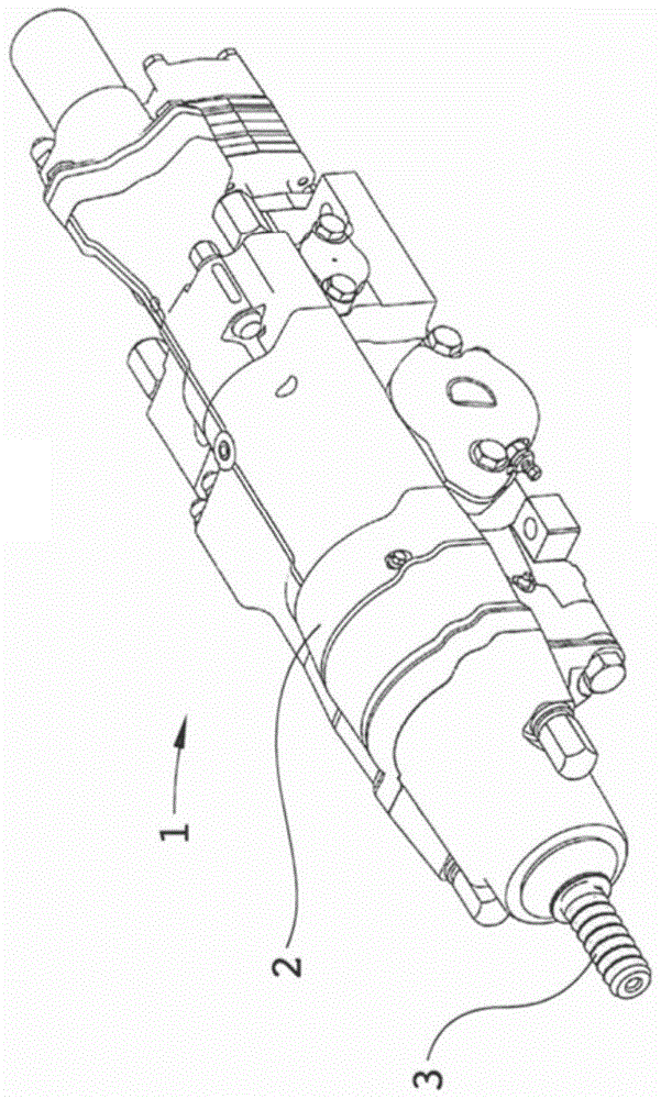
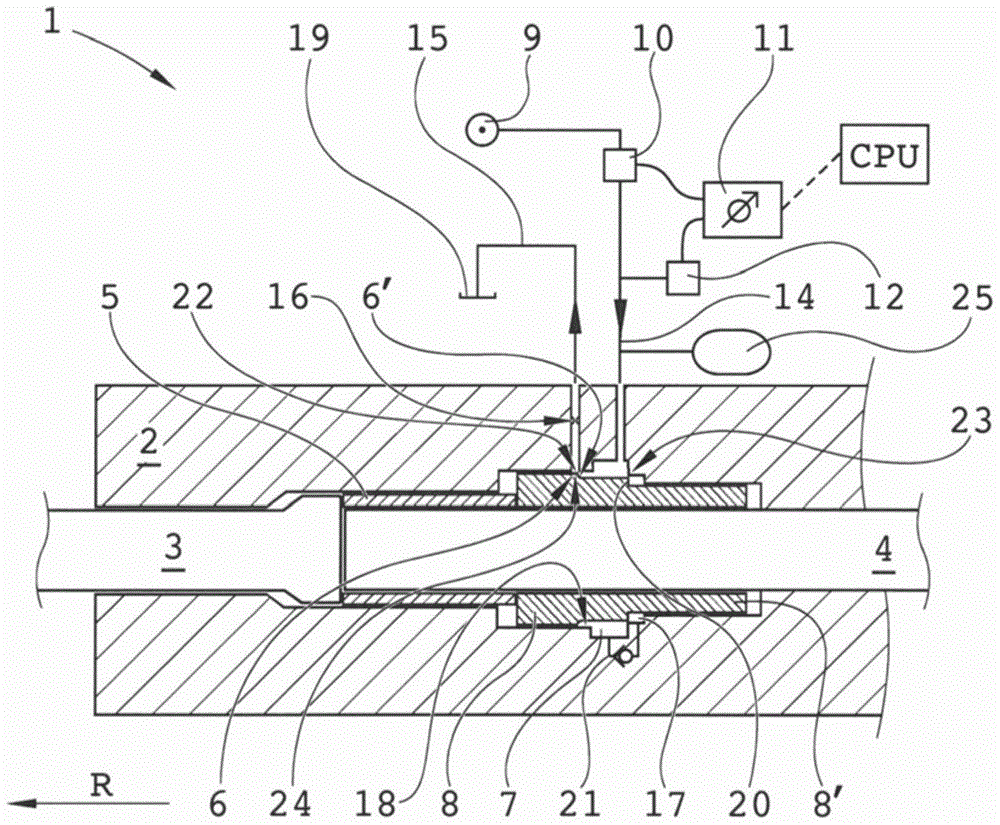
[0036] figure 1 with figure 2 The rock drill 1 according to the present invention is shown in a perspective view and an axial section, respectively, wherein 2 indicates the housing of the rock drill and 3 indicates a shank rod adapter for connecting to drill steel to form a drill string.

[0037] Generally, the rock drill 1 is provided with a striking piston 4 for intermittent striking action on the shank rod adapter 3. A drill sleeve 5 is also applied against the shank rod adapter 3, which is pressed in the striking direction with the aid of a buffer piston 8 in a manner known per se. The purpose of the buffer is, for example, to receive and buffer the reflected shock waves that occur during drilling. Due to the impact of the impact piston, in some operating conditions, depending on the characteristics of the rock, for example, a shock wave reflection tending to drive the shank adapter in a direction opposite to the striking direction R occurs, the shock wave reflection being v...


PUM


Abstract

Damping device for a percussion device of a rock drilling machine (1) having a striking direction (R), including a damping piston (8) for action in an axial direction against a tool to be driven by the percussion device, wherein the damping piston (8) exhibits a piston portion (6), which is received in a damping chamber (7) whereto is connected a damping flow circuit including a supply conduit (14), and wherein an outlet conduit (15) is connected to the damping chamber. A damping flow regulator (10) being controllable in respect of damping flow in the damping flow circuit is arranged in said supply conduit (14), and a control means (11) is arranged to emit control signals to the damping flow regulator (10) for regulating said damping flow. The invention also concerns a percussion device, a rock drilling machine and a method.

Description

Technical field [0001] The present invention relates to a buffer device for an impact device of a rock drill. The buffer device includes a buffer piston received in a buffer chamber, a buffer flow circuit including a supply duct is connected to the buffer chamber, and wherein the outlet duct is also connected to The buffer room. The invention also relates to a buffering method, an impact device and a rock drill. Background technique [0002] The purpose of the buffer device for the impact device of a rock drill is essentially to protect the rock drill and the drill steel from harmful reflected shock waves that occur during drilling. The buffer device is also intended to provide enhanced performance for transmitting the feed force of the drill steel to the rock by ensuring rock contact during drilling. [0003] Previously known from US 4,993,504 is a buffer device for an impact machine, the buffer device comprising a first chamber connected to a reservoir and a second chamber for ...

Claims


Application Information

Patent Timeline
Patent Type & Authority Patents(China)
IPC IPC(8): B25D17/24E21B1/26E21B19/08
CPCB25D9/12B25D9/20B25D17/245B25D2209/005B25D2250/195E21B6/04B25D9/10B25D17/24E21B1/26E21B19/08
Inventor 乔纳斯·亨利松埃里克·阿尔登本特·法尔克乔纳斯·辛纳斯塔德
Owner EPIROC ROCK DRILLS AB
Learn More