medical holding arm

A technology for retaining arms and retaining parts, applied in the connection of rods, medical science, surgical instrument support, etc., can solve problems such as restrictions, and achieve the effect of reducing pressure per unit area

Active Publication Date: 2017-06-16
MAQUET GMBH
View PDF1 Cites 0 Cited by
  • Summary
  • Abstract
  • Description
  • Claims
  • Application Information

AI Technical Summary

Problems solved by technology

[0006] It has been reliably proven in practical applications that a retaining arm operating with a latch of the above-mentioned type is subject to certain restrictions in view of high-load applications

Method used


Image

  • medical holding arm
  • medical holding arm
  • medical holding arm

Examples


Embodiment Construction

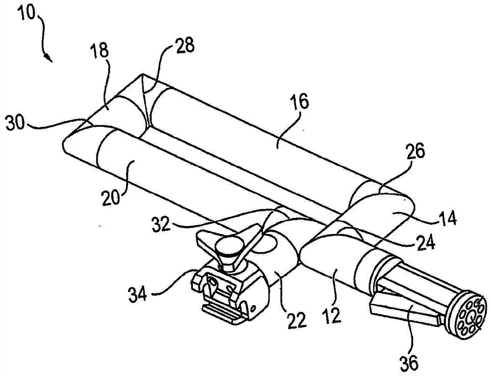
[0029] figure 1 A holding arm 10 is shown which has a plurality of rigid holding parts 12 , 14 , 16 , 18 , 20 and 22 which are coupled to one another via joints 24 , 26 , 28 , 30 and 32 . At one end of the holding arm 10 there is provided a fastening device 34 for mounting the holding arm 10 on a slide rail (not shown) of the operating table. At the other end of the holding arm 10 there is a handle 36 which can be manually actuated by the user in order to unlock the holding arm 10 .

[0030] If no actuating force is applied to the handle 36 , the holders 12 , 14 , 16 , 18 , 20 and 22 of the holder arm 10 are rigidly coupled to one another via the joints 24 , 26 , 28 , 30 and 32 . In this state, the holding arm 10 forms a rigid unit.

[0031] If the user presses the handle 36, the holders 12, 14, 16, 18, 20 and 22, which are coupled to each other via the joints 24, 26, 28, 30 and 32, can move relative to each other via the unlocking mechanism, so that the user can The holdin...


PUM


Abstract

The invention relates to a medical holding arm, comprising at least one joint (24, 26, 28, 30, 32) with two joint bodies (40, 42), which are mutually mutually movable about an axis of rotation (D). Torsion, wherein the first joint body (40) of the joint body has a plurality of locking pins (46) and the second joint body (42) of the joint body has a plurality of locking recesses (48), the locking The number of the pins (46) is different from the number of the latching recesses (48), the latching pins (46) respectively have an axially tapered engaging portion (66), and the latching recesses (48) are respectively axially tapered Tapered for selectively, latching joints (24, 26, 28, 30, 32) to selectively receive each of said engagement portions (66), and at joints (24, 26, 28, 30, 32) During locking, at least one of the latching pins (46) with its tapered engagement portion (66) is completely accommodated in one of the tapered latching recesses (48), while at least one of the other latches The locking pin ( 46 ) with its tapered engagement portion ( 66 ) is only partially received in one of the other tapered latching recesses ( 48 ). The engagement portion (66) of the corresponding latching pin (46) has at least one flattened first abutment surface (68), and the corresponding latching recess (48) has at least one flattened second abutment surface (72). ). The first and second abutment surfaces (68, 72) are at least partially in surface contact with each other when the engagement portion (66) of the corresponding latching pin (46) is received in the corresponding latching recess (48).

Description

technical field [0001] The invention relates to a medical holding arm. Background technique [0002] Currently, for surgical applications there is an increasing use of auxiliary systems comprising, for example, articulated arms which can be mounted on slide rails of operating tables. Such holding arms are used, for example, for arm support during shoulder surgery. The holding arm has a plurality of rigid holding parts which are movably coupled to one another via joints. As a result, the holding arm can move freely in all spatial directions and is held securely in the desired position. [0003] The joints, which respectively couple the two rigid holding parts of the holding arm to one another in a freely movable manner, have a first joint body connected to a holding part and a second joint body connected to the second joint body. Another holder is connected. In order to secure the two holding parts to one another in the desired configuration, the two joint bodies must be ...

Claims


Application Information

Patent Timeline
Patent Type & Authority Patents(China)
IPC IPC(8): A61B90/14A61G13/12F16D1/12F16C11/10F16C11/00
CPCA61B90/50A61B2090/508F16B7/0433F16B21/20F16B9/07F16M11/2007F16M2200/024F16M2200/065Y10T403/32418Y10T403/32581F16B7/02F16M11/06F16B2200/50F16M13/022F16C11/10F16D11/14A61B17/00F16D1/12
Inventor U·维斯鲁查S·彼得
Owner MAQUET GMBH
Why Eureka
Try Eureka