Mechanically controllable valve drive arrangement

A transmission mechanism, mechanical control technology, applied in the direction of machine/engine, mechanical equipment, engine components, etc., can solve problems such as inability to re-establish valve lift, inability to adjust, and unsatisfactory engine operating characteristics

Inactive Publication Date: 2014-10-15
KOLBENSCHMIDT PIERBURG INNOVATIONS GMBH
View PDF5 Cites 0 Cited by
  • Summary
  • Abstract
  • Description
  • Claims
  • Application Information

AI Technical Summary

Problems solved by technology

However, all of these valve trains have the disadvantage that after manufacture and subsequent assembly, due to manufacturing tolerances, it is not possible to adjust to or re-establish the exact desired valve lift in working condition.
Especially when a uniform valve lift is required for all valves and cylinders of a multi-cylinder internal combustion engine, this can lead to unsatisfactory running characteristics of the engine at small valve lifts

Method used


Image

  • Mechanically controllable valve drive arrangement
  • Mechanically controllable valve drive arrangement

Examples


Embodiment Construction

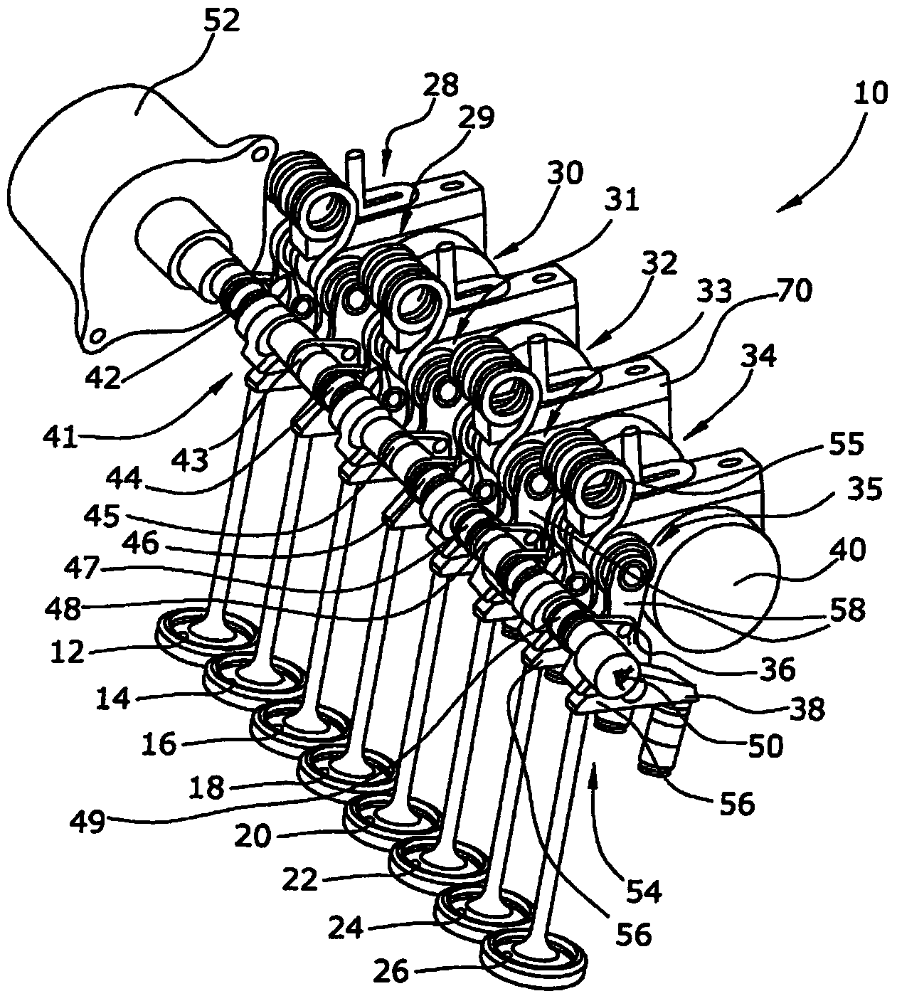
[0012] figure 1 An embodiment of the valve train 10 according to the invention is shown, comprising a plurality of gas exchange valves 12 , 14 , 16 , 18 , 20 , 22 , 24 and 26 arranged in a row. In the illustrated case, every two intake valves are assigned to a cylinder of the internal combustion engine. The mechanically controllable valve train 10 has four transmission devices 28, 29, 30, 31, 32, 33 and 34, 35 in the present embodiment, for which two gas exchange valves 12, 14 are assigned respectively; 16, 18; 20, 22; 24, 26. Here, the transport devices 28 , 29 , 30 , 31 , 32 , 33 and 34 , 35 are mounted in a known manner on the cylinder head by means of bearing devices. exist figure 1 The support devices 36 , 38 for supporting the rocker 56 of the transport device 35 are only shown by way of example. In addition, the transmission devices 28 , 29 , 30 , 31 , 32 , 33 and 34 , 35 are operatively connected to the camshaft 40 in a known manner. In addition, each transmission...


PUM


Abstract

The invention relates to a mechanically controllable valve drive arrangement (10) having a plurality of gas exchange valves (12, 14, 16, 18, 20, 22, 24, 26) disposed in a row, wherein a transmission arrangement (28, 29, 30, 31, 32, 33, 34, 35) is associated with a gas exchange valve (12, 14, 16, 18, 20, 22, 24, 26), wherein the transmission arrangement (28, 29, 30, 31, 32, 33, 34, 35) has at least one intermediate lever arrangement (58) and at least one pivot lever arrangement (56), wherein an intermediate lever (64) of the intermediate lever arrangement (58) has a working cam (60) for operatively connecting to a pivot lever (72) of the pivot lever arrangement (56), wherein the intermediate lever (64) is operatively connected to a peripheral contour of a camshaft (40) and wherein the intermediate lever arrangement (58) has an engagement element (80); which is operatively connected to a valve lift adjustment device (41), wherein the valve lift adjustment device (41) has a control shaft (50) which acts on a first end (76) of an adjusting lever (74), wherein the second end (78) is operatively connected to the engagement element (80) of the intermediate lever arrangement (58).

Description

technical field [0001] The invention relates to a mechanically controllable valve train, comprising a plurality of gas exchange valves arranged in a row, which belong to the corresponding cylinder, wherein a transmission device is assigned to a gas exchange valve, wherein the transmission device has at least one an intermediate lever arrangement and at least one rocker arrangement, wherein the intermediate lever of the intermediate lever arrangement has a working surface (Arbeitskurve) for operative connection with the rocker of the rocker arrangement, wherein the intermediate lever is operatively connected to the peripheral contour of the camshaft, In addition, the intermediate lever device has an engagement element which is operatively connected to the valve lift adjustment device. Background technique [0002] Such valve trains are known in detail. For example, DE 10 2006 033 559 A1 and DE 10 2007 022 266 A1 describe valve drives which have an adjustable lift height for ...

Claims


Application Information

Patent Timeline
IPC IPC(8): F01L13/00
CPCF01L13/0063F01L2013/0068F01L13/0021F01L2105/00F01L13/0026F01L2305/00
Inventor M.诺瓦克K.格里姆M.布吕尔
Owner KOLBENSCHMIDT PIERBURG INNOVATIONS GMBH
Why Eureka
Try Eureka