
Battery charging control device based on boost circuit

A booster circuit, battery charging technology, applied in circuit devices, battery circuit devices, current collectors, etc., can solve problems such as shortening battery life, and achieve the effects of extending service life, good reliability, and wide operating voltage range

Inactive Publication Date: 2015-07-01
WUXI CITY CHONGAN DISTRICT TECH ENTREPRENEURSHIP SERVICE CENT
View PDF5 Cites 4 Cited by
  • Summary
  • Abstract
  • Description
  • Claims
  • Application Information

AI Technical Summary

Problems solved by technology

The charging device of the invention can not only charge the bluetooth device, turn the charged bluetooth device into sleep mode to reduce power consumption, and establish a communication channel for the communicating bluetooth device at the same time, but due to the back and forth charging of the battery, the battery is used shortened lifespan

Method used


Image

  • Battery charging control device based on boost circuit
  • Battery charging control device based on boost circuit

Examples


Embodiment Construction

[0019] Below in conjunction with accompanying drawing, technical scheme of the present invention is described in further detail:

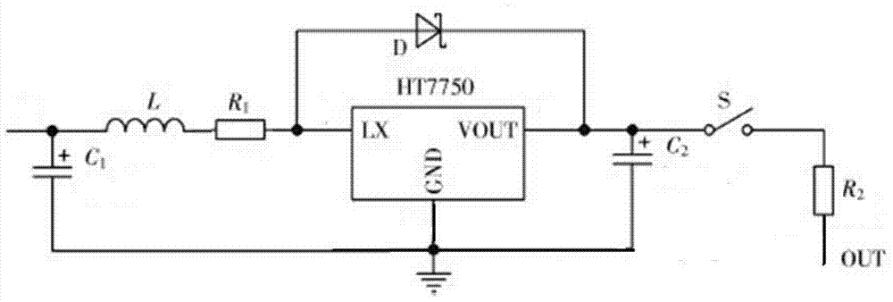
[0020] Such as figure 1 As shown, a battery charging control device based on a boost circuit includes a solar photovoltaic panel, a boost circuit, a charging circuit, a power supply module and a comparator; the output end of the solar photovoltaic panel is connected to the input end of the boost circuit, and the boost circuit The output terminal of the voltage circuit is connected to the input terminal of the charging circuit, the output terminal of the charging circuit is connected to the input terminal of the power module, the output terminal of the power module is connected to the input terminal of the comparator, and the output terminal of the comparator is connected to the charging circuit ; Among them, the comparator is used to compare the battery output voltage with the set value in real time, and then control the opening and closing of the...


PUM


Abstract

The invention discloses a battery charging control device based on a boost circuit. The device comprises a solar panel, the boost circuit, a charging circuit, a power supply module and a comparable; the output end of the solar panel is connected to the input end of the boost circuit, the output end of the boost circuit is connected to the input end of the charging circuit, the output end of the charging circuit is connected to the input end of the power supply module, the output end of the power supply module is connected to the input end of the comparable, and the output end of the comparable is connected to the charging circuit. The comparable is used for comparing the battery output voltage with a set value to control the charging circuit to power on and off. The power supply module adopts solar energy and is capable of analyzing the battery voltage state in real time so as to charge the battery intelligently; the service life of a node is prolonged effectively.

Description

technical field [0001] The invention relates to a charging control system, in particular to a battery charging control device based on a voltage boosting circuit, which belongs to the field of electric energy recovery. Background technique [0002] At present, many batteries are being charged back and forth, and repeated charging for a long time will reduce the service life of the battery. How to make the battery charge when it reaches the maximum power usage, and avoid unnecessary charging operations. In order to charge the secondary battery, a charging device is used. The charging method in this charging device is generally performed based on the voltage output from the secondary battery and the voltage at which the secondary battery is charged. For example, the output voltage of the secondary battery is used to determine whether the secondary battery is in a fully charged state. It is checked whether the output voltage is greater than or equal to a predetermined value X...

Claims


Application Information

Patent Timeline
Patent Type & Authority Applications(China)
IPC IPC(8): H02J7/00H02S10/20
CPCH02J7/35H02S40/00Y02E10/50Y02E70/30
Inventor 叶强陈伟新潘琳
Owner WUXI CITY CHONGAN DISTRICT TECH ENTREPRENEURSHIP SERVICE CENT
Learn More