Eureka AIR delivers breakthrough ideas for toughest innovation challenges, trusted by R&D personnel around the world.

Method for positioning microseism event point

A microseismic and event point technology, applied in seismic signal processing and other directions, can solve the problems of low resolution of positioning data and low positioning accuracy of fracturing wells with lateral velocity changes

Active Publication Date: 2015-07-01
BC P INC CHINA NAT PETROLEUM CORP +1
View PDF8 Cites 15 Cited by
  • Summary
  • Abstract
  • Description
  • Claims
  • Application Information

AI Technical Summary

Problems solved by technology

[0003] An exemplary embodiment of the present invention is to provide a method for locating microseismic event points, which can solve the problem that the positioning data of existing microseismic event point locating methods have low resolution in the depth direction and are relatively difficult for deep formations and underground structures. The positioning accuracy of fractured well areas with complex or severe lateral velocity changes is not high

Method used


Image

  • Method for positioning microseism event point
  • Method for positioning microseism event point
  • Method for positioning microseism event point

Examples


Embodiment Construction

[0027] Reference will now be made in detail to the exemplary embodiments of the present invention, examples of which are illustrated in the accompanying drawings, wherein like numerals refer to like parts throughout. The exemplary embodiments are described below in order to explain the present invention by referring to the figures.

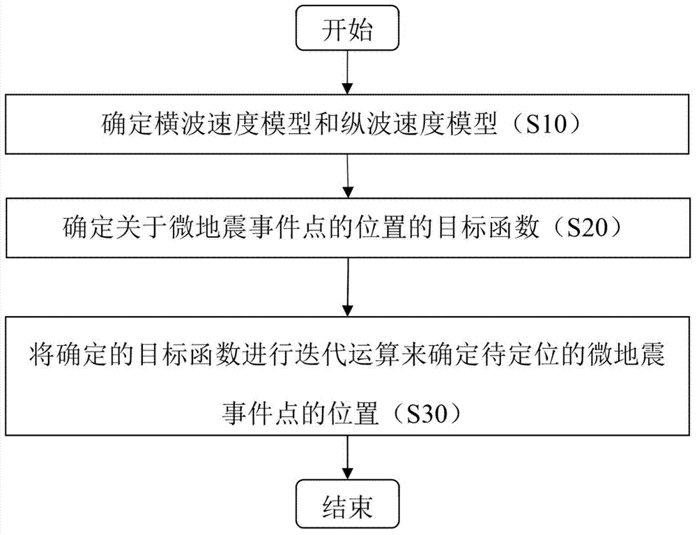
[0028] figure 1 A flowchart showing a method for locating microseismic event points according to an exemplary embodiment of the present invention.

[0029] refer to figure 1 , in step S10, determine the shear wave velocity model and the compressional wave velocity model according to the acoustic logging data, the first arrival time of the shear wave from the scheduled perforation to the geophone, and the first arrival time of the compressional wave from the scheduled perforation to the geophone. Here, the shear wave velocity model indicates the relationship between the shear wave velocity of the microseismic event point to the geophone and the p...


PUM


Abstract

The invention provides a method for positioning a microseism event point. The method comprises the following steps: (a) determining a cross wave speed model and a longitudinal wave speed model according to acoustic logging data, a cross wave first arrival time from a predetermined perforation hole to a wave detector and a longitudinal wave first arrival time from the predetermined perforation hole to the wave detector; (b) determining a target function of the position about the microseism event point according to the cross wave speed model, the longitudinal wave speed model, the longitudinal wave actual first arrival time from the microseism event point to be positioned to every wave detector, and the cross wave actual first arrival time from the microseism event point to be positioned to every wave detector; (c) determining position of the microseism event point to be positioned by iterative operation on determined target function. The method for positioning the microseism event point avoids the problem of low resolution rate on depth direction for only adopting the positioning data of the longitudinal wave information, and improves the microseism positioning precision.

Description

technical field [0001] The present invention generally relates to the technical field of microseismic ground monitoring, and more specifically, relates to a method for locating microseismic event points. Background technique [0002] At present, in the field of hydraulic fracturing microseismic ground monitoring technology, the microseismic event point location technology is generally based on layered velocity models or uniform velocity models. For fracturing wells with relatively simple underground structures and small lateral velocity changes, Accurate position, but there are obvious positioning errors for fracturing well areas with deep formations, complex underground structures or severe lateral velocity changes; in terms of positioning methods, the method of superposition of longitudinal wave energy is generally used, which will make the positioning data The resolution is lower in the depth direction. Contents of the invention [0003] An exemplary embodiment of the ...

Claims


Application Information

Patent Timeline
IPC IPC(8): G01V1/28
Inventor 尹陈康亮刘鸿袁枫尧刘丽婷巫芙蓉曹立斌蔡谦胡光岷赵尧
Owner BC P INC CHINA NAT PETROLEUM CORP
Why Eureka
Eureka Blog
Learn More