
Antifreeze method and device for unit unit in air conditioning system

An air-conditioning system and unit technology, applied in the direction of heating, mechanical equipment, space heating and ventilation, etc., can solve the problems of increased unit unit cost, compressor loss, non-standard water system design, etc., to achieve simple antifreeze protection, prevent damage effect

Active Publication Date: 2018-10-16
GD MIDEA HEATING & VENTILATING EQUIP CO LTD +1
View PDF6 Cites 0 Cited by
  • Summary
  • Abstract
  • Description
  • Claims
  • Application Information

AI Technical Summary

Problems solved by technology

[0003] The air conditioning system includes a unit unit, and the unit unit usually includes a water-side heat exchanger, or is arranged in parallel (that is, the water inlet of the water-side heat exchanger is connected to the water inlet of the unit unit, and the outlet of the water-side heat exchanger The water outlets are all connected to the water outlet of the unit unit), and the water side heat exchanger is an important refrigeration accessory. Sometimes due to poor design protection measures of the unit unit and irregular design of the water system during engineering installation, etc. , it often occurs that the water side heat exchanger shell tube and the heat exchange tube freeze due to the low water flow rate and the evaporation pressure is too low, resulting in the cold medium heat exchange tube being compressed by the frozen ice and bursting, which will eventually make the refrigeration system Internal leaks cause losses due to burning of the compressor. Therefore, the antifreeze protection of the unit unit is very important, but the antifreeze protection methods in the prior art usually need to increase the cost of the unit unit, or the antifreeze protection method is complicated and not easy to implement

Method used


Image

  • Antifreeze method and device for unit unit in air conditioning system
  • Antifreeze method and device for unit unit in air conditioning system
  • Antifreeze method and device for unit unit in air conditioning system

Examples


Embodiment Construction

[0037] The specific implementation manners of the present invention will be further described in detail below in conjunction with the accompanying drawings and embodiments. The following examples are used to illustrate the present invention, but are not intended to limit the scope of the present invention.

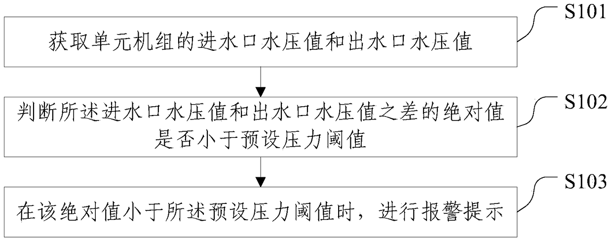
[0038] figure 1 It is a flow chart of the anti-freezing method for the unit unit in the air-conditioning system of an embodiment of the present invention; refer to figure 1 , the method includes:

[0039] S101: Obtain the water inlet water pressure value and the water outlet water pressure value of the unit unit;

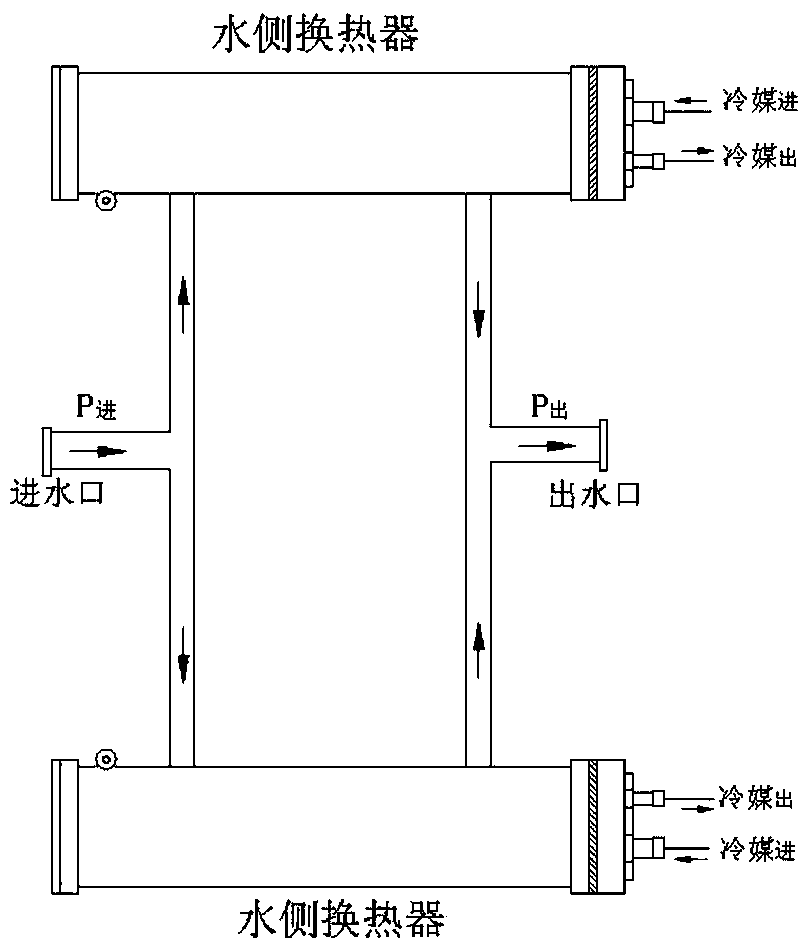
[0040] It should be noted that the water pressure value of the water inlet can be collected by a water pressure sensor arranged at the water inlet of the unit unit, and correspondingly, the water pressure value of the water outlet can be collected by the water pressure sensor arranged at the outlet of the unit unit. The water pressure sensor of the water outl...


PUM


Abstract

The invention discloses an anti-freezing method and device for a unit in an air conditioning system, and relates to the field of air conditioning technologies. The method includes the steps that the water inlet water pressure value and the water outlet water pressure value of the unit are acquired; whether the absolute value of the difference between the water inlet water pressure value and the water outlet water pressure value is smaller than a preset pressure threshold value; when the absolute value is smaller than the preset pressure threshold value, an alarm is given. According to the method, when the absolute value of the difference between the water inlet water pressure value and the water outlet water pressure value is smaller than the preset pressure threshold value, the alarm is given, so that the situation that because the unit operates under severe working conditions, a water side heat exchanger is frozen to damage is avoided, anti-freezing protection for the unit is easily and conveniently achieved without increasing the cost of the unit too much, and the situation that because the whole unit is damaged, the unit can not operate is avoided.

Description

technical field [0001] The invention relates to the technical field of air conditioning, in particular to an antifreezing method and device for a unit unit in an air conditioning system. Background technique [0002] In regions rich in water resources, more and more customers choose air-conditioning systems that use water and refrigerant as heat-exchange media to meet the needs of cooling and heating. Such air-conditioning systems are convenient for water intake and save operating costs. [0003] The air conditioning system includes a unit unit, and the unit unit usually includes a water-side heat exchanger, or is arranged in parallel (that is, the water inlet of the water-side heat exchanger is connected to the water inlet of the unit unit, and the outlet of the water-side heat exchanger The water outlets are all connected to the water outlet of the unit unit), and the water side heat exchanger is an important refrigeration accessory. Sometimes due to poor design protection...

Claims


Application Information

Patent Timeline
Patent Type & Authority Patents(China)
IPC IPC(8): F24F11/32F24F11/52F24F11/64
CPCF24F11/30F24F2110/00
Inventor 王立友
Owner GD MIDEA HEATING & VENTILATING EQUIP CO LTD
Learn More