
Synchronous lifting control system for hydraulic cylinders

A control system and synchronous lifting technology, which is applied in fluid pressure actuation system testing, fluid pressure actuation devices, servo motors, etc., can solve the problems of adjustment accuracy relying on visual inspection, synchronous control of lifting hydraulic cylinders, and box tilting. Achieve the effect of increasing safety, improving precision, and smooth lifting and lowering

Inactive Publication Date: 2015-07-01
SICHUAN NANJUN AUTOMOBILE GROUP
View PDF5 Cites 9 Cited by
  • Summary
  • Abstract
  • Description
  • Claims
  • Application Information

AI Technical Summary

Problems solved by technology

[0003] At present, the cabinet of the garbage compressor uses two hydraulic cylinders to realize lifting and lowering. Among them, the hydraulic system is only controlled by two sets of three-position four-way solenoid valves. This method cannot realize synchronous control of the lifting hydraulic cylinders, resulting in The cabinet is seriously tilted, and manual adjustment is required to solve the tilt problem
In practice, the inclination of the box is controlled by manually adjusting the stroke of the lifting hydraulic cylinder. The workload is large, the process is cumbersome, and the adjustment accuracy depends on visual inspection. The error is large and it is easy to cause damage to the machine parts.

Method used


Image

  • Synchronous lifting control system for hydraulic cylinders
  • Synchronous lifting control system for hydraulic cylinders

Examples


Embodiment Construction

[0023] In order to enable those skilled in the art to better understand the technical solutions of the present invention, the present invention will be further described in detail below in conjunction with specific examples.

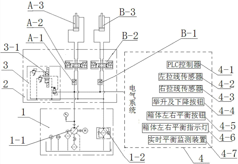
[0024] Such as figure 1 As shown, the hydraulic cylinder synchronous lifting control system of the present application includes a hydraulic station 1, a valve mounting support 2, a bipolar electromagnetic overflow valve 3, and a branch oil circuit A and a branch oil circuit B.

[0025] Branch oil circuit A is provided with left speed control valve A-1, left three-position four-way solenoid valve A-2, left hydraulic cylinder A-3 from front to back; branch oil circuit B is provided with right speed control valve from front to back B-1, right three-position four-way solenoid valve B-2, right hydraulic cylinder B-3;

[0026] Bipolar electromagnetic overflow valve 3, left speed regulating valve A-1, right speed regulating valve B-1, left three-position four-...


PUM


Abstract

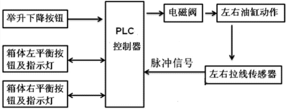
The invention discloses a synchronous lifting control system for hydraulic cylinders. The synchronous lifting control system comprises a hydraulic station, a double-pole electromagnetic overflow valve, a valve installation support, two branch oil ways and an electrical system. Speed regulation valves, three-position four-way electromagnetic valves and the hydraulic cylinders are sequentially arranged on the two branch oil ways from front to back. Each speed regulation valve is a two-way flow control valve formed by connecting a throttling valve and a uniform-pressure drop valve in series. A real-time balance monitoring device is added to the electrical system, and therefore once unbalance happens, corresponding actions are executed. The hydraulic cylinders responsible for lifting and putting down a trash compressor box body can be independently controlled, the cylinders do not interfere with each other during work, and accuracy is improved. In addition, flow flowing through the speed regulation valves is not influenced by changes of loads, the movement speeds of the hydraulic cylinders are not changed when the loads are changed, and it is automatically ensured that the trash compressor box body is stably lifted and put down; meanwhile, the defect that the human cost is increased when a box body severely inclines and manual regulation is needed is overcome, and safety is improved.

Description

technical field [0001] The invention belongs to the field of hydraulic control systems, and in particular relates to a hydraulic cylinder synchronous lifting control system. Background technique [0002] With the urbanization of our country, the composition of urban domestic waste has undergone great changes, the density of garbage has been decreasing, and the compressibility has increased. The workload of garbage disposal in cities has become more and more heavy. The traditional way of manual garbage collection is adopted. , time-consuming and labor-intensive, and inefficient. Garbage compactors have begun to receive attention and are used more and more widely. [0003] At present, the cabinet of the garbage compressor uses two hydraulic cylinders to realize lifting and lowering. Among them, the hydraulic system is only controlled by two sets of three-position four-way solenoid valves. This method cannot realize synchronous control of the lifting hydraulic cylinders, res...

Claims


Application Information

Patent Timeline
Patent Type & Authority Applications(China)
IPC IPC(8): F15B11/22F15B19/00
CPCF15B11/08F15B19/00
Inventor 胡杰徐长福陈家平
Owner SICHUAN NANJUN AUTOMOBILE GROUP
Learn More