Discharging bin for particle materials and absorption tower device with discharging bin

A granular material and silo technology, which is applied in the field of path structure design of granular material flow, can solve the problem of inconsistent discharge speed, etc., and achieve the effect of guaranteed operation effect and reliable operation effect.

Inactive Publication Date: 2015-07-01
ZHONGYE-CHANGTIAN INT ENG CO LTD
View PDF6 Cites 0 Cited by
  • Summary
  • Abstract
  • Description
  • Claims
  • Application Information

AI Technical Summary

Problems solved by technology

[0006] In view of this, it is urgent to optimize the design of the structure of the existing discharge bin, on the basis of ensuring the basic functions, to overcome the defect of inconsistent discharge speed in the same section

Method used


Image

  • Discharging bin for particle materials and absorption tower device with discharging bin
  • Discharging bin for particle materials and absorption tower device with discharging bin
  • Discharging bin for particle materials and absorption tower device with discharging bin

Examples


Embodiment 1

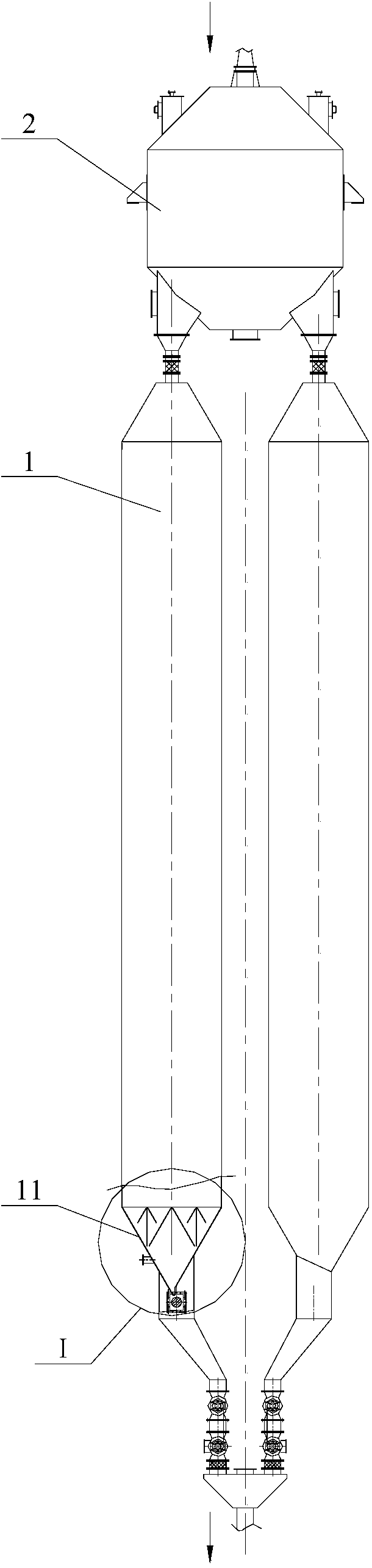
[0034] See figure 2 , which is a schematic diagram of the overall structure of the analytical tower device described in this embodiment.

[0035] The analysis tower device includes two analysis tower main bodies 1, so as to control the safety height of the tower body on the basis of satisfying the system analysis capability. The activated carbon that has been adsorbed is sent to the upper feeding bin 2 through the conveyor, and the activated carbon to be decomposed is output to the two desorption tower main bodies 1 through the feeding channel of the feeding bin 2 respectively. The same as the prior art, in the two desorption tower main bodies 1, the activated carbon in the desorption tower is indirectly heated by the heat medium, and the activated carbon is kept in the high temperature zone (320-490° C.) for a certain period of time, so that the adsorbed SO 2 Decompose and discharge harmful substances at high temperature, the adsorption function of activated carbon can be r...

Embodiment 2

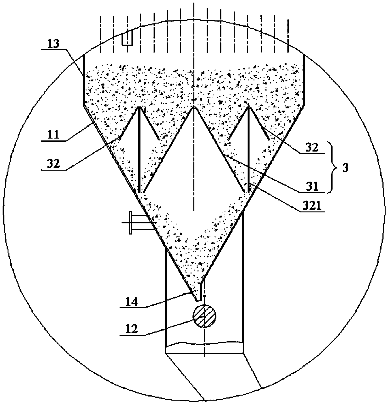
[0048] The current equalization and discharge mechanism 3 of the discharge bin provided in this embodiment is configured as a three-stage current equalization component. For details, please refer to Figure 4 , which shows a schematic structural view of the discharge bin described in this embodiment.

[0049] Compared with the first embodiment, the difference of this solution is that a third-level current equalizing part 33 is added. In order to clearly show the difference and connection between this solution and the first embodiment, components with the same function in the figure are marked with the same symbols . As shown in the figure, there are four third-level current equalization parts 33 (n=3), which are the same as the second-level current equalization parts 32, and each third-level current equalization part 33 is respectively arranged on the second-level current equalization part. The middle part of the formed parallel cavity area, thus the corresponding area is div...


PUM


Abstract

The invention relates to the technical field of path structural design of particle material flowing, and provides a discharging bin for particle materials and an absorption tower device with the discharging bin. The discharging bin is shrunk inwards from a containing body to the bottom and forms a lower end discharging port. A uniform flow discharging mechanism is arranged in the discharging bin and is provided with n levels of integrally big-end-down uniform flow components in a projection plane perpendicular to the length direction of the discharging port, 2n-1 uniform flow components are arranged in each level, and n is a positive integer. The first level of uniform flow components are arranged in the middle of the discharging bin, and the upper portion of the discharging bin is divided into two parallel containing cavity areas. All 2-nth level uniform flow components are sequentially arranged in the middle of the parallel containing area formed by the uniform flow components formed in the previous level and are correspondingly separated into two level parallel containing cavity areas. By means of the discharging bin, the flowing speed of materials in the same section of the discharging bin is roughly the same, and therefore the duration for all the materials to flow through the discharging bin can be controlled to be basically the same.

Description

technical field [0001] The invention relates to the technical field of path structure design for the flow of granular materials, in particular to a discharge bin for granular materials and an analytical tower device using the discharge bin. Background technique [0002] The adsorption tower and the desorption tower are the two main reaction places of activated carbon desulfurization and denitrification technology. The two organically cooperate to complete the adsorption of harmful substances in the exhaust flue gas, as well as the regeneration and activation of activated carbon; SO in 2 , NO X and other harmful gases. Therefore, on the basis of meeting the requirements of flue gas emission, high-concentration SO can be recycled. 2 , while realizing the recycling of activated carbon. [0003] As we all know, the regeneration and activation technology of activated carbon that has adsorbed harmful substances mainly includes two methods: dosing analysis and heating analysis. ...

Claims


Application Information

Patent Timeline
Patent Type & Authority Applications(China)
IPC IPC(8): B65D88/54B65D90/00
CPCB65D88/54B65D90/00
Inventor 傅旭明肖中元
Owner ZHONGYE-CHANGTIAN INT ENG CO LTD
Why Eureka
Try Eureka