
An automatic lighting controller

A controller and light sensor technology, applied in optical signals, signaling devices, transportation and packaging, etc., can solve the problems of the driver being unable to see the road ahead, affecting the driver of the preceding vehicle, hidden dangers of traffic accidents, etc., so as to reduce the driving intensity , The status judgment is accurate, and the effect of ensuring safety

Active Publication Date: 2017-07-18
安徽天健环保车辆部件有限公司
View PDF7 Cites 0 Cited by
  • Summary
  • Abstract
  • Description
  • Claims
  • Application Information

AI Technical Summary

Problems solved by technology

[0002] At present, the operation mode of automobile headlights is manual control. In the process of vehicles meeting at night, it is often encountered that the other party comes to turn on the high beam. Blind, the other driver can't see the road ahead, there is a great potential for traffic accidents; when the rear vehicle turns on the high beam, a large area of ​​halo will appear in the interior and exterior rearview mirrors of the vehicle in front, which will affect the driving of the vehicle in front The driver observes the rear situation from the rearview mirror
When driving uphill and downhill at night, the lights of cars traveling in the opposite direction and the reflected light from the road surface will affect the driver's vision. If it is too strong, the driver will not be able to see the road ahead, so the driver needs to manually switch the car in time. High and low beams, some car manufacturers have equipped their own models with automatic headlight control systems to automatically control the switching of high and low beams. Most of them are expensive and have simple functions.

Method used


Image

  • An automatic lighting controller
  • An automatic lighting controller
  • An automatic lighting controller

Examples


Embodiment Construction

[0023] The present invention will be described in further detail below in conjunction with the accompanying drawings and specific embodiments.

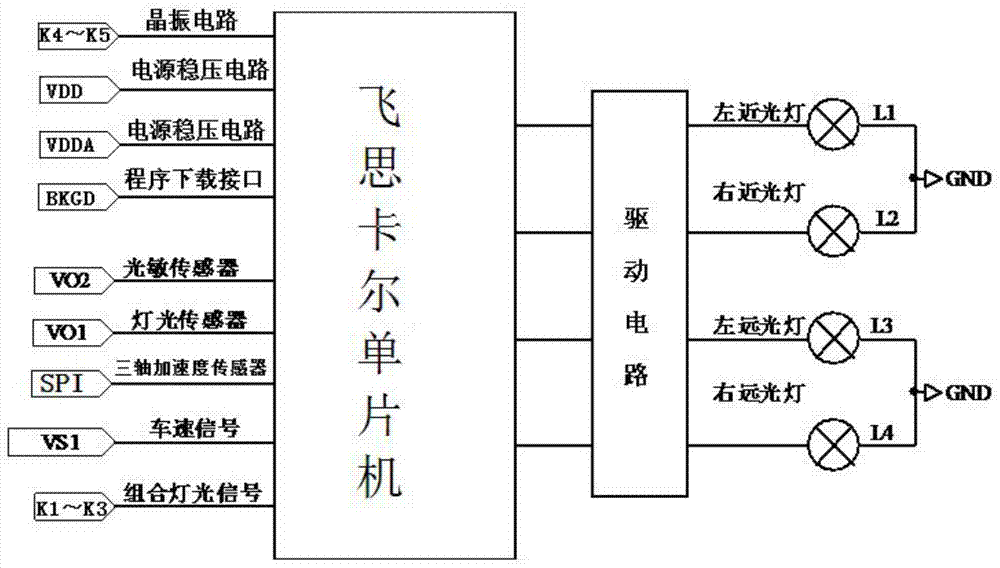
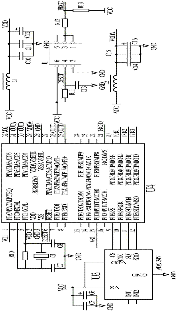
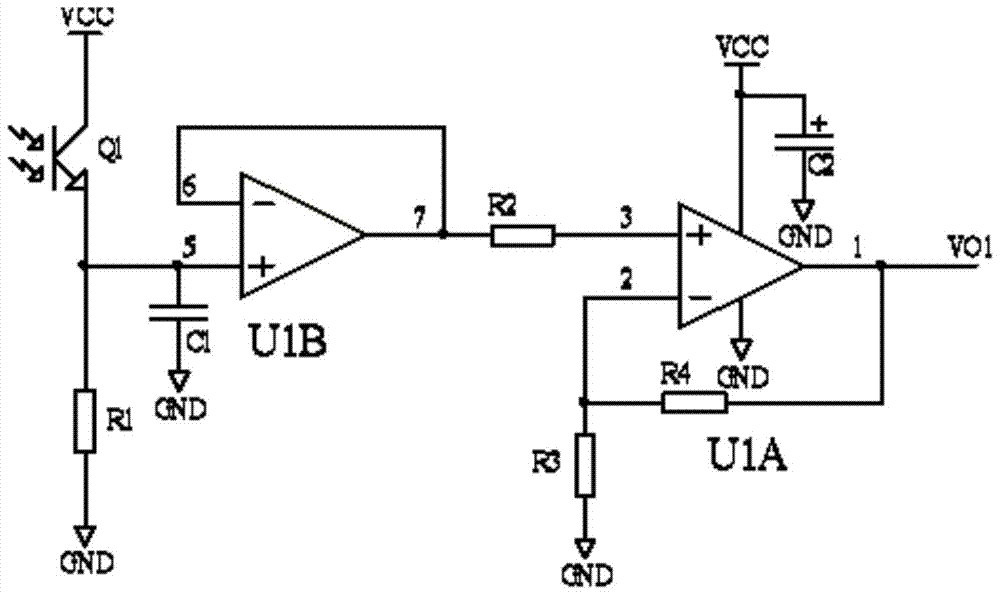
[0024] Such as figure 1 or figure 2 As shown, an automatic light controller, the automatic light controller includes a control circuit, a photosensitive sensor, a light sensor, a three-axis acceleration sensor U3, a vehicle speed signal, a combined light signal, a driving circuit, a low beam, a high beam, etc. , the control circuit includes an external power supply input circuit connected to the input terminal of the single-chip microcomputer U4, a crystal oscillator circuit, and a program download interface circuit, and the output terminals of the photosensitive sensor, light sensor, vehicle speed signal, and combined light signal are connected to the input terminal of the single-chip microcomputer U4, The three-axis acceleration sensor U3 is connected to the single-chip microcomputer U4 through the SPI interface, and the output en...


PUM


Abstract

An automatic light controller, the automatic light controller includes a control circuit, a photosensitive sensor, a light sensor, a three-axis acceleration sensor U3, a vehicle speed signal, a combined light signal, a drive circuit, a low beam, a high beam, etc., the The control circuit includes an external power supply input circuit connected to the input terminal of the single-chip microcomputer U4, a crystal oscillator circuit, and a program download interface circuit. The output terminals of the photosensitive sensor, light sensor, vehicle speed signal and combined light signal are connected to the input terminal of the single-chip microcomputer U4. The output end of the axial acceleration sensor U3 is connected to the SPI interface of the single-chip microcomputer, and the output end of the control circuit is connected to the low beam and the high beam through the driving circuit. The invention can automatically control the lighting or closing of the headlights of the automobile according to the change of the ambient light intensity, avoiding the potential safety hazards caused by frequent dimming or constant dimming to safe driving, and ensuring the safety of driving at night.

Description

technical field [0001] The invention relates to the field of automatic control of automobiles, in particular to an automatic light controller. Background technique [0002] At present, the operation mode of automobile headlights is manual control. In the process of vehicles meeting at night, it is often encountered that the other party comes to turn on the high beam. Blind, the other driver can't see the road ahead, there is a great potential for traffic accidents; when the rear vehicle turns on the high beam, a large area of ​​halo will appear in the interior and exterior rearview mirrors of the vehicle in front, which will affect the driving of the vehicle in front The driver observes the situation behind from the rearview mirror. When driving uphill and downhill at night, the lights of cars traveling in the opposite direction and the reflected light from the road surface will affect the driver's vision. If it is too strong, the driver will not be able to see the road ahe...

Claims


Application Information

Patent Timeline
Patent Type & Authority Patents(China)
IPC IPC(8): B60Q1/14B60Q1/08
Inventor 马智慧吴成加何申文吴亚群管理松
Owner 安徽天健环保车辆部件有限公司
Learn More