Steel bar bender and use method thereof

A technology for steel bar bending and bending axis, which is applied in the field of steel bar bending machines, can solve problems such as inability to bend metal pipes, low efficiency of single bending, and out-of-round steel bars, and achieve the effects of simple and convenient configuration of tooling, improvement of work efficiency, and cost savings in use

Inactive Publication Date: 2015-07-01
CHINA METALLURGICAL CONSTR ENG GRP
View PDF7 Cites 8 Cited by
  • Summary
  • Abstract
  • Description
  • Claims
  • Application Information

AI Technical Summary

Problems solved by technology

[0003] The existing steel bar bending machine has the following defects in the use process: one is that the single bending work efficiency is low in the processing of steel bars, the other is that the positioning of multiple steel bars is poor when bending, and there is a phenomenon that the steel bars are out of round after bending; Rebar Equal Diameter Metal Pipe

Method used


Image

  • Steel bar bender and use method thereof
  • Steel bar bender and use method thereof
  • Steel bar bender and use method thereof

Examples


Embodiment 1

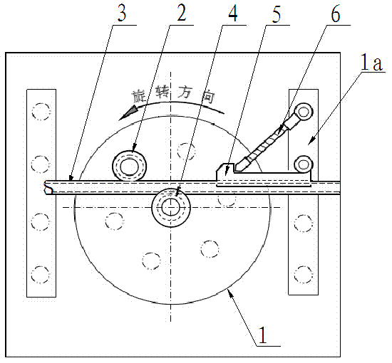
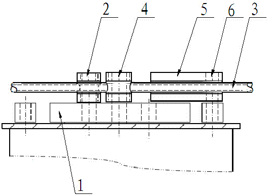
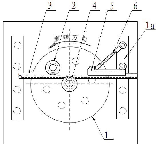
[0023] Example 1: see Figure 1 to Figure 4 , a steel bar bending machine, comprising a machine tool and a transmission mechanism installed on it, the upper part of the machine tool is connected to the transmission mechanism, and a working disc 1 driven to rotate by the transmission mechanism is provided with a positioning plate 1a and a feeding roller, and The positioning plate 1a and the feeding roller are symmetrically arranged on both sides of the working disc 1. Specifically, the positioning plate 1a is preferably made of square steel, which is not only convenient for installation, but also facilitates the installation of the positioning plate 5 (detailed below). Has a central shaft hole and a curved shaft hole.

[0024] The central shaft hole is located at the center of the working disk 1, and a central pile sleeve wheel 4 is installed in the central shaft hole, and the outer surface of the central pile sleeve wheel 4 has a first groove arranged along its circumference...

Embodiment 2

[0027] Example 2: A method of using a steel bar bending machine, the steel bar bending machine is described in embodiment 1;

[0028] Step 1: According to the description in Embodiment 1, a plurality of first grooves are processed on the outer surface of the central pile sleeve wheel 4, and a plurality of second grooves are processed on the outer surface of the auxiliary pile guide wheel 2. When the plate 5 is in use, a plurality of third grooves are processed towards the side of the central pile sleeve wheel 4;

[0029] Step 2: Then install the central pile sleeve wheel 4 in the center shaft hole, install the auxiliary pile guide wheel 2 in the curved shaft hole, install the positioning baffle plate 5 between the positioning plate 1a and the working disc 1, and adjust the screw rod 6 is installed between the positioning baffle plate 5 and the square steel 1a;

[0030] Step 3: Pass the straight steel bar or metal pipe 3 to be bent through the first groove, the second groove...


PUM


Abstract

The invention relates to a steel bar bender and a use method thereof. The steel bar bender comprises a working disc, which is arranged on the upper portion of a machine tool and drivingly matched with a transmission mechanism; the working disc is provided with a central shaft hole and a bent shaft hole; the central shaft hole is provided with a central pile casing wheel, and the outer surface of the central pile casing wheel is provided with a circumferentially arranged first groove; the bent shaft hole is provided with an auxiliary pile guide wheel, and the outer surface of the auxiliary pile guide wheel is provided with a circumferentially arranged second groove. The steel bar bender also comprises a positioning baffle between a positioning plate and the working disc, and the side surface of the positioning baffle, which faces towards the central pile casing wheel when in use, is provided with a third groove. By means of the first groove, the second groove and the third groove, the steel bar bender can avoid sliding of straight steel bars during a bending process and prolong the service life, and meanwhile, can ensure the bending precision and during bending operation, can achieve the effects of avoiding out-of-circularity of the straight steel bars as well as ensuring equal diameter of bent sections of non-bent sections.

Description

technical field [0001] The invention relates to a steel bar processing machine, in particular to a steel bar bending machine and a using method thereof. Background technique [0002] The steel bar bending machine is a kind of mechanical equipment for bending straight steel bars, which is mainly used in construction and other industries. Generally, the steel bar bending machine includes a hollow shell for installing the motor and the transmission gear. The lower part of the shell is equipped with several pulleys. The steel bar bending machine can move freely under the action of the pulleys. There are a working disc, a positioning plate and a roller, wherein the working disc is provided with a central shaft hole and several curved shaft holes, the central shaft hole is used to install the central pile sleeve wheel, and the curved shaft hole is used to install the auxiliary pile guide wheel. The steel bar is bent under the joint action of the machine tool support pin, the cent...

Claims


Application Information

Patent Timeline
Patent Type & Authority Applications(China)
IPC IPC(8): B21F1/00B21D7/04
CPCB21F1/00B21D7/04
Inventor 陈国民
Owner CHINA METALLURGICAL CONSTR ENG GRP
Why Eureka
Try Eureka