Adjustable bracket for sliding rail assembly

A slide rail assembly and bracket technology, applied in the bracket field

Active Publication Date: 2015-06-24
KING SLIDE WORKS CO LTD +1
View PDF8 Cites 21 Cited by
  • Summary
  • Abstract
  • Description
  • Claims
  • Application Information

AI Technical Summary

Problems solved by technology

[0003] The above-mentioned previous case is a general rack server, but now the server is developing towards high density, and some specific servers require more components to be packed in a limited space. In this case, the use of the operating space of the slide rail Therefore, the related components of the slide rail must be adjusted accordingly to meet the needs of the server installed on the rack.

Method used


Image

  • Adjustable bracket for sliding rail assembly
  • Adjustable bracket for sliding rail assembly
  • Adjustable bracket for sliding rail assembly

Examples


Embodiment Construction

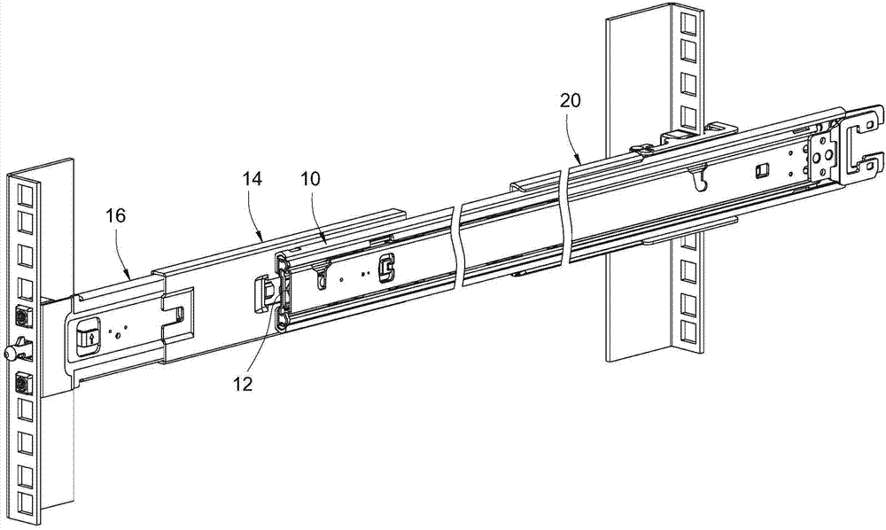
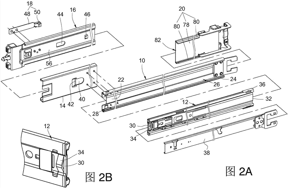
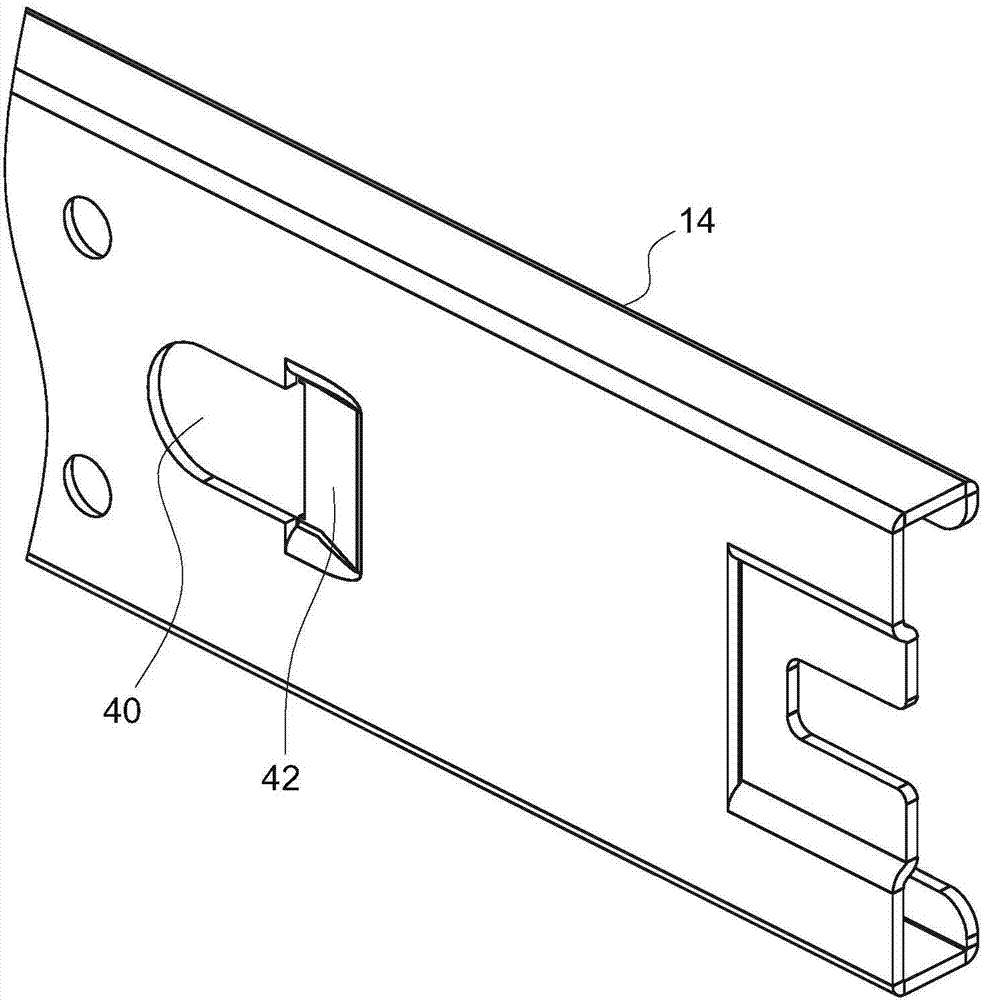
[0028] Such as figure 1 , Figure 2A and Figure 2B As shown, the slide rail assembly of the embodiment of the present invention includes: a first rail 10, a second rail 12, a support member 14, a first bracket 16, a latch 18, and a second support 架20.

[0029] The first rail 10 has a front end 22, a rear end 24, defining a passage 26, and a first limiting portion 28 located in the passage 26 adjacent to the front end 22.

[0030] The second rail 12 is slidably connected to the first rail 10. The second rail 12 has a front end 30, a rear end 32, a release member 34, and a second limiting portion 36. The release member 34 is located Adjacent to the front end 30 of the second rail 12. The second limiting portion 36 is located adjacent to the rear end 32 of the second rail 12, and the second limiting portion 36 corresponds to the first limiting portion 28 of the first rail 10 and is used to When the rail 12 is pulled out of a position relative to the first rail 10, the second limitin...


PUM


Abstract

The invention relates to an adjustable bracket for a sliding rail assembly. The adjustable bracket comprises a bracket body, a supporting piece and a clamping piece. The bracket body is provided with an opening and an abutting portion. The supporting piece is connected with the bracket body in a sliding mode and provided with a through hole and a stop portion. The stop portion corresponds to the abutting portion. The clamping piece is provided with an elastic arm and a clamping portion, wherein the clamping portion is arranged on the elastic arm and corresponds to the opening of the bracket body. When the supporting piece slides towards the rear side of the bracket body to a preset position, the abutting portion abuts against the stop portion; when the supporting piece slides towards the front side of the bracket body to the through hole and corresponds to the opening, the clamping portion of the clamping piece stretches into the through hole in the supporting piece under the elastic action of the elastic arm so as to clamp the supporting piece.

Description

Technical field [0001] The invention relates to a bracket, in particular to an adjustable bracket for a sliding rail assembly. Background technique [0002] The U.S. invention patent US7,281,694B2 issued to Allen et al. discloses a traditional sliding rail assembly for a server chassis. The rack has a pair of support columns on the left and right sides. Take one pair of support columns as an example. There is a predetermined distance to the support column according to the frame of different depth. A slide rail assembly is installed between the pair of support columns. The slide rail assembly includes an outer rail, a middle rail, an inner rail, a front bracket, and a rear bracket, wherein the outer rail has a A front end and a rear end, the middle rail is slidably connected to the outer rail, the inner rail is slidably connected to the middle rail, the front bracket is fixed to the front end of the outer rail, and the rear bracket is fixed to the rear end of the outer rail. The...

Claims


Application Information

Patent Timeline
Patent Type & Authority Applications(China)
IPC IPC(8): H05K7/14A47B88/04A47B96/06
Inventor 陈庚金杨顺和黄建立王俊强
Owner KING SLIDE WORKS CO LTD
Why Eureka
Try Eureka