
Organic light emitting display and manufacturing method thereof

A technology of light-emitting display and manufacturing method, which is applied in the manufacture of semiconductor/solid-state devices, semiconductor devices, electrical components, etc., can solve the problems of reducing light-emitting efficiency of organic light-emitting display devices, reducing light-emitting efficiency, affecting display quality, etc., and improving light-emitting efficiency. , The effect of improving luminous efficiency and low cost

Active Publication Date: 2015-06-24
KUNSHAN GO VISIONOX OPTO ELECTRONICS CO LTD
View PDF3 Cites 18 Cited by
  • Summary
  • Abstract
  • Description
  • Claims
  • Application Information

AI Technical Summary

Problems solved by technology

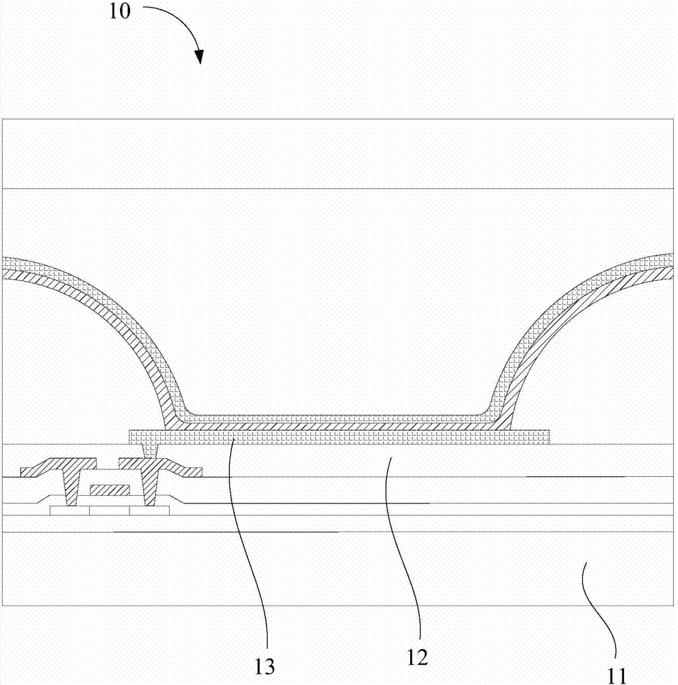
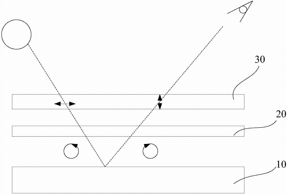
However, because the quarter wave plate 20 is strongly wavelength dependent, effective at some wavelengths and less effective at others, it is not 100% effective
At the same time, due to the existence of the circular polarizer, at least half of the light emitted by the organic light emitting display device is blocked, which greatly reduces the light extraction efficiency of the organic light emitting display device.
[0005] Therefore, one of the cathode and the anode of a traditional organic light-emitting display is a reflective electrode, which reflects external light, resulting in a decrease in contrast and seriously affecting the display quality.
Moreover, the traditional solution is to attach a circular polarizer, but the light extraction efficiency is greatly reduced

Method used


Image

  • Organic light emitting display and manufacturing method thereof
  • Organic light emitting display and manufacturing method thereof
  • Organic light emitting display and manufacturing method thereof

Examples


Embodiment Construction

[0043]In order to facilitate the understanding of the present invention, the present invention will be described more fully below with reference to the associated drawings. Preferred embodiments of the invention are shown in the accompanying drawings. However, the present invention can be embodied in many different forms and is not limited to the embodiments described herein. On the contrary, these embodiments are provided to make the understanding of the disclosure of the present invention more thorough and comprehensive.

[0044] It should be noted that when an element is referred to as being “fixed” to another element, it can be directly on the other element or there can also be an intervening element. When an element is referred to as being "connected to" another element, it can be directly connected to the other element or intervening elements may also be present. In contrast, when an element is referred to as being "directly on" another element, there are no intervenin...


PUM


Abstract

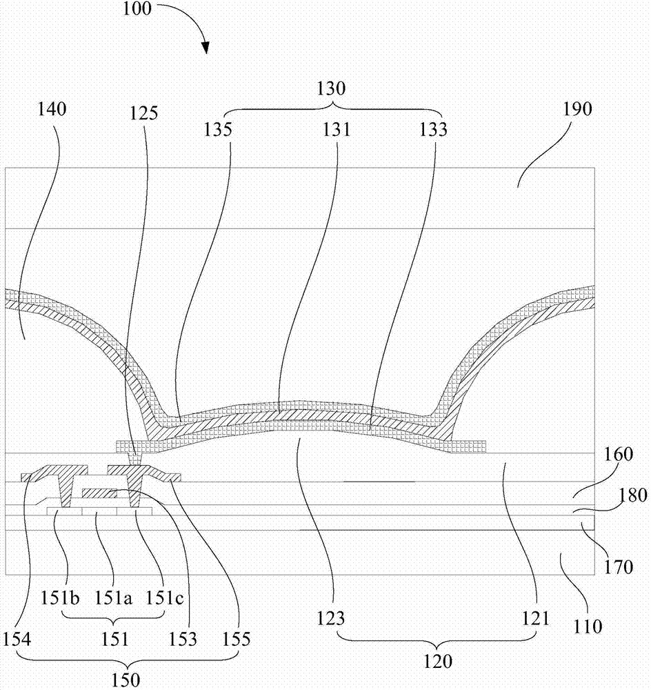
The invention discloses an organic light emitting display and a manufacturing method thereof. The organic light emitting display comprises a flatness layer and an organic light emitting element, wherein the first surface of the flatness layer comprises a flat area and a rugged area connected with the flat area, and the flat area and the rugged area are arranged in a stagger and interval mode; the organic light emitting element comprises an organic light emitting layer and a reflection layer; the organic light emitting layer and the reflection layer are stacked on the rugged area; and the part, corresponding to the rugged area, of the reflection layer is provided with a diffuse reflection part with the same shape as that of the rugged area. According to the above organic light emitting display, the reflection layer with the same shape is formed on the rugged area on the organic light emitting element, and mirror reflection can be effectively controlled; as the reflection layer has a rugged shape, the light emitting area is increased, and the light emitting efficiency per unit area is improved; and in addition, as the reflection layer can effectively control mirror reflection, circular polarizers can be saved or reduced, and the light extraction efficiency is greatly improved.

Description

【Technical field】 [0001] The present invention relates to a display device and a manufacturing method thereof, in particular to an organic light-emitting display device and a manufacturing method thereof. 【Background technique】 [0002] Organic light-emitting display devices (OLEDs) are active light-emitting devices. Compared with the current mainstream flat-panel display technology, thin-film transistor liquid crystal display (TFT-LCD), organic light-emitting display devices have the advantages of high contrast, wide viewing angle, low power consumption, and thinner, and can be used to make flexible displays and transparent displays. It is expected to become the next-generation flat-panel display technology following the liquid crystal display device, and it is the technology that has received the most attention in the flat-panel display technology at present. [0003] Since the organic light emitting display device is a self-luminous device, usually one of the two electro...

Claims


Application Information

Patent Timeline
IPC IPC(8): H01L51/52H01L51/56
Inventor 陆海峰
Owner KUNSHAN GO VISIONOX OPTO ELECTRONICS CO LTD
Learn More