A touch screen positioning method, device and touch screen equipment
A positioning method and touch screen technology, applied in the direction of instruments, electrical digital data processing, data processing input/output process, etc., can solve the problems of low density of optical network, missing touch points, affecting the positioning accuracy of touch points, etc., to achieve increased The effect of optical network density, improving positioning accuracy, and reducing the possibility of omission
- Summary
- Abstract
- Description
- Claims
- Application Information
AI Technical Summary
Problems solved by technology
Method used
Image

Examples
Embodiment 1
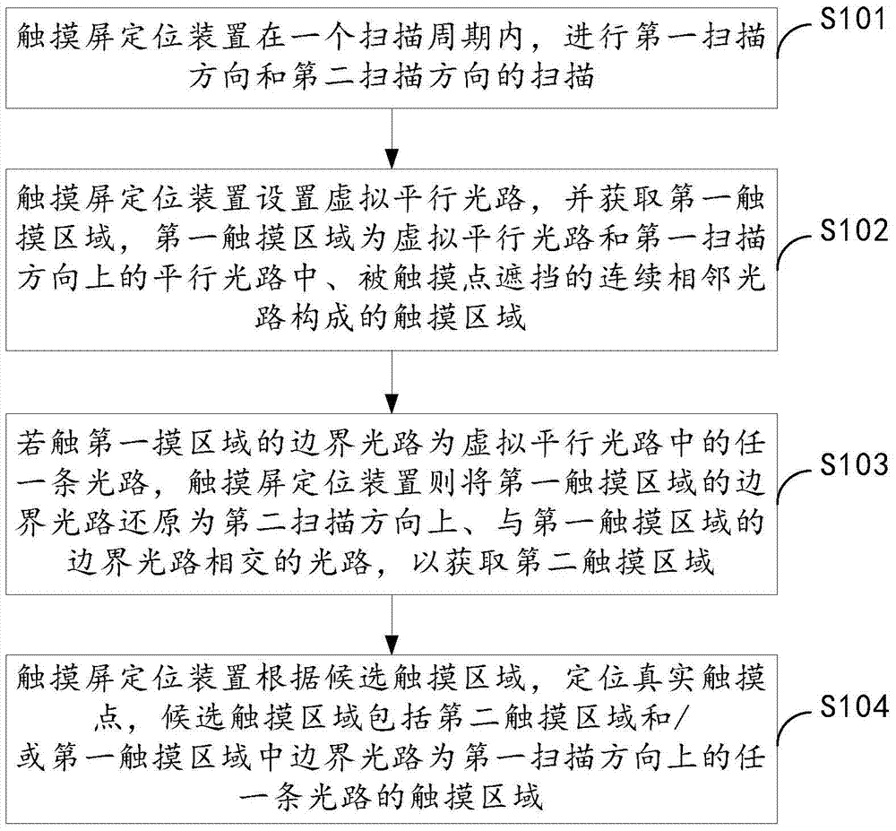
[0054] The embodiment of the present invention provides a touch screen positioning method, which is applied to a touch screen device. The touch screen of the touch screen device includes a first direction edge and a second direction edge, such as image 3 As shown, the touch screen positioning method includes:
[0055] S101. The touch screen positioning device performs scanning in the first scanning direction and the second scanning direction in one scanning period.
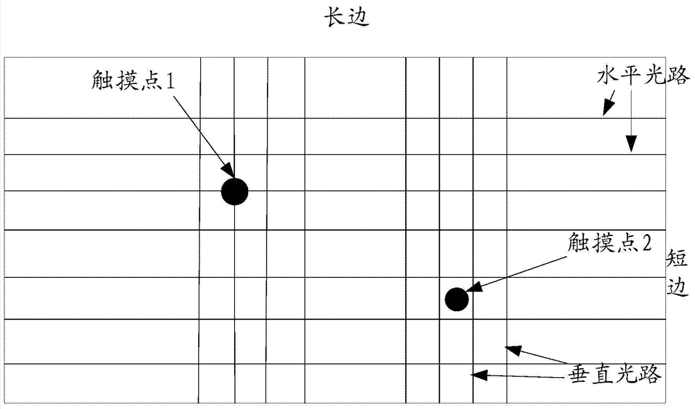
[0056] Wherein, the first scanning direction is any scanning direction on the first direction side or the second direction side. The first scanning direction includes a group of parallel light paths including the first optical path, and the second scanning direction includes a group including the second The parallel light path of the optical path; the emitting lamp of the second optical path is the same as the emitting lamp of the first optical path, and the receiving lamp of the second optical path is adjacent to the ...
Embodiment 2
[0077] The embodiment of the present invention provides a touch screen positioning method, which is applied to a touch screen device. The touch screen of the touch screen device includes a first direction edge and a second direction edge, such as Figure 13 Shown, including:
[0078] S201. The touch screen positioning device performs scanning in the first scanning direction and the second scanning direction in one scanning period.
[0079] The first scanning direction is either the first direction side or the second direction side. The first scanning direction includes a set of parallel optical paths including the first optical path, and the second scanning direction includes a set of parallel optical paths including the second optical path. Parallel optical path; the emitting lamp of the second optical path is the same as the emitting lamp of the first optical path, and the receiving lamp of the second optical path is adjacent to the receiving lamp of the first optical path; or, th...
Embodiment 3
[0147] The embodiment of the present invention provides a touch screen positioning device, which is included in a touch screen device. The touch screen of the touch screen device includes a first direction edge and a second direction edge, such as Figure 26 As shown, the touch screen positioning device includes: a scanning unit 31, a light path setting unit 32, an acquisition unit 33, a light path restoration unit 34, and a positioning unit 35.
[0148] The scanning unit 31 is configured to perform scanning in a first scanning direction and a second scanning direction within one scanning period, where the first scanning direction is any scanning direction on the first direction side or the second direction side, The first scanning direction includes a set of parallel optical paths including a first optical path, and the second scanning direction includes a set of parallel optical paths including a second optical path; the emission lamp of the second optical path is connected to th...
PUM
 Abstract
Description
Claims
Application Information
 - R&D
- Intellectual Property
- Life Sciences
- Materials
- Tech Scout
- Unparalleled Data Quality
- Higher Quality Content
- 60% Fewer Hallucinations
Browse by: Latest US Patents, China's latest patents, Technical Efficacy Thesaurus, Application Domain, Technology Topic, Popular Technical Reports.
© 2025 PatSnap. All rights reserved.Legal|Privacy policy|Modern Slavery Act Transparency Statement|Sitemap|About US| Contact US: help@patsnap.com