Rotor blade and guide vane airfoil for a gas turbine engine

A technology for rotor blades and gas turbines, used in engine components, engine manufacturing, engine function, etc., to solve problems such as drag loss, head loss, and obstructed flow, to improve heat transfer, good performance, and reduce cooling air consumption Effect

Inactive Publication Date: 2015-06-24
ANSALDO ENERGIA SWITZERLAND AG
View PDF8 Cites 2 Cited by
  • Summary
  • Abstract
  • Description
  • Claims
  • Application Information

AI Technical Summary

Problems solved by technology

Any elements protruding from the end walls, i.e. pin fins and ribs, will impede flow, creating drag losses and head losses in the system

Method used


Image

  • Rotor blade and guide vane airfoil for a gas turbine engine
  • Rotor blade and guide vane airfoil for a gas turbine engine
  • Rotor blade and guide vane airfoil for a gas turbine engine

Examples


Embodiment Construction

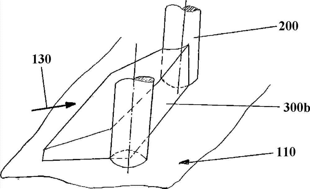
[0061] refer to figure 1 , the cooling channel 100a is provided in a rotor blade or guide vane (in the following, indicated by a rotor blade for simplicity) of a gas turbine to send a cooling medium 130 thereinto. The inner wall of the flow cooling path 100 is covered by the heat exchange walls 110a and 111a, wherein the pins (see figure 2 ) is disposed near the inner side of the cooling passage 100a. The structure of the heat exchange walls 110a and 111a may be the same as that of any other cooling path 101a, 102a.

[0062] When the gas turbine is operated, high-temperature gas 120 is blown toward the rotor blades, and the rotor blades rotate around a rotation axis (not shown). A cooling medium 130 is supplied into the cooling channel 100a from the base portion of the rotor blade. Cooling medium 130 takes heat away from the rotor blades and is exhausted to path 131 through which high temperature gas 120 flows. The heat exchange walls 110 a , 111 a are disposed on the inn...


PUM


Abstract

The invention refers to a rotor blade or guide vane airfoil for a gas turbine engine having a longitudinal axis and a source of cooling fluid, the airfoil having a pressure wall, a suction wall, a leading edge, a trailing edge and at least one cooling fluid flow passage. The cooling fluid flow passage is in fluid communication with the source of cooling fluid. Means for directing cooling fluid at least to the trailing edge are provided, whereas the cooling fluid flow passage including: a plurality of axially extending walls, each of the walls extending laterally between the pressure wall and suction wall. The plurality of walls being radially spaced within the cooling fluid flow passage such that adjacent pairs of walls define a channel, the axial spacing between the adjacent walls comprising in radial direction of the airfoil a pins and a ribs structure, wherein the pins holistic or approximately cover the axial height of the channel. The ribs have a deeper level with respect to the pins and the ribs establish a bridge-like connection between each of adjacent ribs.

Description

technical field [0001] The present invention relates to the field of heat transfer characteristics of flow channels having pins and ribs with improved heat transfer coefficients. [0002] A rotor blade or vane airfoil for a gas turbine engine having a longitudinal axis and a source of cooling fluid, the airfoil having a pressure wall, a suction wall, a leading edge, a trailing edge and at least one cooling fluid flow passage , and the cooling fluid flow channel is in fluid communication with the cooling fluid source, and provides means for guiding the cooling fluid to at least the trailing edge, wherein the cooling fluid flow channel includes: a plurality of axially extending walls, each wall at extending laterally between the pressure wall and the suction wall, wherein a plurality of walls are radially spaced within the cooling fluid flow path such that adjacent pairs of walls define channels, wherein the axial spacing between adjacent walls A pin and rib structure is includ...

Claims


Application Information

Patent Timeline
Patent Type & Authority Applications(China)
IPC IPC(8): F01D5/18F01D9/02
CPCF01D5/187F01D9/02F05D2250/292F05D2260/2212F05D2260/22141
Inventor J. 克鲁伊克斯M. 维德梅
Owner ANSALDO ENERGIA SWITZERLAND AG
Why Eureka
Try Eureka