Grouting connecting structure of prefabricated part and construction method thereof

A technology of prefabricated components and grouting connections, which is applied to the processing of building components, building structures, and building materials. It can solve problems such as failure to detect in time, evaporation and loss of grouting material moisture, and achieve the effect of convenient observation.

Active Publication Date: 2015-06-24
CHINA CONSTR EIGHT ENG DIV CORP LTD
View PDF6 Cites 14 Cited by
  • Summary
  • Abstract
  • Description
  • Claims
  • Application Information

AI Technical Summary

Problems solved by technology

The current general practice is to select the vent hole at the bottom of a certain grouting sleeve as the grouting hole, and use a grouting gun or a grouting pump to complete the grouting. This method has certain disadvantages: (1) Since the grouting process is a pressurized operation, after the grouting nozzle is removed , it will inevitably cause the liquid level in the sleeve to drop, resulting in the grouting at the top of the sleeve is not dense; (2) due to the evaporation or loss of water in the grouting material, it may cause the liquid level in the grouting sleeve to drop, but it cannot be found in time, resulting in the top of the sleeve Grouting is not dense

Method used


Image

  • Grouting connecting structure of prefabricated part and construction method thereof
  • Grouting connecting structure of prefabricated part and construction method thereof
  • Grouting connecting structure of prefabricated part and construction method thereof

Examples


Embodiment Construction

[0028] The present invention will be described in further detail below with reference to the accompanying drawings and specific embodiments.

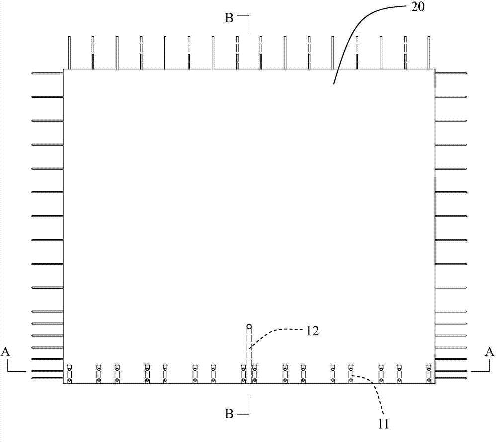
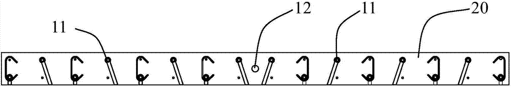
[0029] see first Figures 1 to 3 As shown, the grouting connection structure of the prefabricated component of the present invention is mainly composed of a grouting sleeve 11 embedded in the bottom of the prefabricated component 20 for inserting butt-jointed steel bars, and an observation tube 12 embedded in the bottom of the prefabricated component 20 .

[0030] Cooperate Figure 4 and Figure 5 As shown, the grouting sleeve 11 in this embodiment is a half grouting sleeve, and it is also applicable to other grouting sleeves such as full grouting sleeves. Insertion, the interior of the grouting sleeve 11 forms a grouting space, the lower part of the grouting sleeve 11 is provided with a grouting port 111, the upper part of the grouting sleeve 11 is provided with a grouting port 112, and the grouting port 111 and the grouting port 11...


PUM


Abstract

The invention discloses a grouting connecting structure of a prefabricated part and a construction method thereof. The grouting connecting structure comprises grouting sleeves and an observation pipe, wherein the grouting sleeves are arranged at the bottom of the prefabricated part in an embedded mode and serve for insertion of butt-joint reinforcing steel bars, a grouting port is formed in the lower portion of the sleeve wall of each grouting sleeve, a grout discharge port is formed in the upper portion of the sleeve wall of each grouting sleeve, and grouting holes and grout discharge holes corresponding to the grouting ports and the grout discharge ports are formed in the prefabricated part; the observation pipe is arranged at the bottom of the prefabricated part in an embedded mode, a pipe port at a first end of the observation pipe is formed in the end face of the bottom of the prefabricated part, a pipe port at a second end of the observation pipe is formed in the surface of the side wall of the prefabricated part, and the arrangement location of the pipe port located at the second end of the observation pipe is higher than the top positions of the grouting sleeves. According to the grouting connecting structure of the prefabricated part and the construction method thereof, by pre-embedding the observation pipe at the lower end of the prefabricated part, the grouting sleeves and the observation pipe are filled with grout, by means of the intrinsic pressure of the filling grout, automatic grout replenishment is completed when the liquid level at the tops of the grouting sleeves declines, and the observation pipe is utilized for raising the grout liquid level, so that it is convenient for workers to make observation, the grout is replenished in time, and the grout compactness is guaranteed.

Description

technical field [0001] The invention relates to the technical field of engineering construction, in particular to a grouting connection structure of prefabricated components and a construction method thereof. Background technique [0002] For prefabricated shear walls connected by grouting sleeves, vertical steel bars need to be connected by grouting the grouting sleeves. The current general practice is to select the exhaust hole at the bottom of a grouting sleeve as the grouting hole, and use the grouting gun or grouting pump to complete the grouting. This method has certain disadvantages: (1) Since the grouting process is a pressure operation, after the grouting nozzle is removed , it will inevitably cause the liquid level in the sleeve to drop, resulting in the grouting at the top of the sleeve is not dense; (2) Due to the evaporation or loss of water in the grouting material, the liquid level in the grouting sleeve may drop, but it cannot be found in time, resulting in t...

Claims


Application Information

Patent Timeline
Patent Type & Authority Applications(China)
IPC IPC(8): E04B2/00E04G21/00E04G21/02
Inventor 郭志鑫马荣全苗冬梅孙学锋范新海牛辉陈丝琳刘亚男徐晨姚鲁朱庆涛
Owner CHINA CONSTR EIGHT ENG DIV CORP LTD
Why Eureka
Try Eureka