a thread tie

A technology of wire tying and limiting pressure plate is applied to wire tying. It can solve the problems of low reuse rate of wire ties, inability to reuse, and inability to connect, so as to achieve the effect of fixing and reuse, and improving the rate of reuse.

Active Publication Date: 2017-11-24
GREE ELECTRIC APPLIANCES INC
View PDF8 Cites 0 Cited by
  • Summary
  • Abstract
  • Description
  • Claims
  • Application Information

AI Technical Summary

Problems solved by technology

[0004] However, the clamping hole of the wire tie body 13 and the clamping part 12 is a one-time fixed connection, that is, the two cannot be disassembled after being connected or cannot be reconnected after being disassembled, resulting in that the wire tie can only be used once and cannot be reused. Makes the bundle less reusable
[0005] In addition, after the fixing part 14 is fixed, it is necessary to cut off the excess part of the tail of the wire binding body 13, resulting in more cumbersome wire fixing and lower wire fixing efficiency

Method used


Image

  • a thread tie
  • a thread tie
  • a thread tie

Examples


Embodiment Construction

[0030] The embodiment of the present invention provides a wire bundle, which can realize repeated use, thereby improving the reuse rate of the wire bundle.

[0031] The following will clearly and completely describe the technical solutions in the embodiments of the present invention with reference to the accompanying drawings in the embodiments of the present invention. Obviously, the described embodiments are only some, not all, embodiments of the present invention. Based on the embodiments of the present invention, all other embodiments obtained by persons of ordinary skill in the art without making creative efforts belong to the protection scope of the present invention.

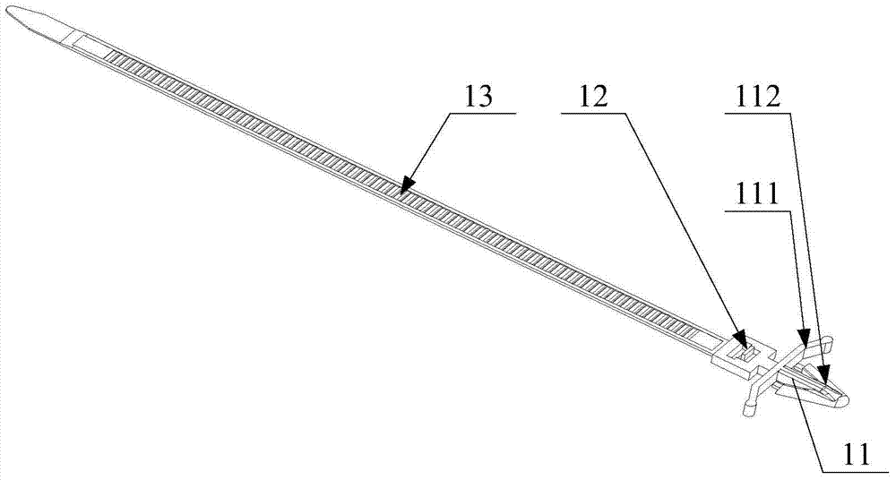
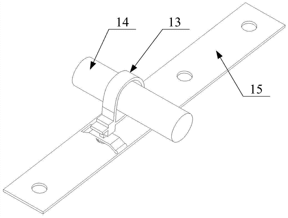
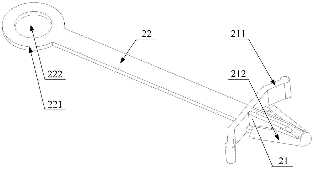
[0032] The wire binding provided by the embodiment of the present invention includes: a wire binding head 21 and a wire binding body 22 connected to the wire binding head 21; 211 connected to the bottom end of the clip 212 that can be clamped with the base plate 23; wherein, the wire tie body 22 has a fas...


PUM


Abstract

The invention provides a wire tie, comprising: a wire tie head and a wire tie body connected to the wire tie head; The clamping head clamped by the base plate; wherein, the wire tie body has a tightening part capable of being limited to the bottom end of the limiting platen, and the tightening part has a through hole for the clamping head to pass through. In the wire tie provided by the present invention, the tightening part can be limited to the bottom of the limiting platen, which ensures the tightness of the wire tie to the fixed parts; The non-destructive disassembly of the part and the clamp head can realize the fixing and repeated use of the fixing part, thereby improving the reusable rate of the wire bundle.

Description

technical field [0001] The invention relates to the technical field of wire binding, and more specifically, relates to a wire binding. Background technique [0002] Wire tying is widely used due to its fast binding, good insulation, self-locking fastening, and convenient use. Currently, there is a wire tie such as figure 1 As shown, the wire binding includes: a wire binding head 11 clamped to the substrate 15 , a clamping portion 12 connected to the wire binding head 11 and having a clamping hole, and a wire binding body 13 connected to the clamping portion 12 . Wherein, the wire binding body 13 can pass through the clamping hole of the clamping part 12 and be clamped with the clamping hole; the wire binding head 11 includes: a limiting pressure plate 111 of the limiting substrate 15, and is connected with the bottom end of the limiting pressure plate 111 and connected with the clamping hole. The clamp head 112 clamped by the substrate 15 , the clamp head 112 has a limitin...

Claims


Application Information

Patent Timeline
Patent Type & Authority Patents(China)
IPC IPC(8): B65D63/16
Inventor 陈国强潘耀权黄茂科刘建东梁绍吉吕华冲
Owner GREE ELECTRIC APPLIANCES INC
Why Eureka
Try Eureka