
DLP three-dimensional printer and three-dimensional printing method

A 3D printer and 3D printing technology, applied in the direction of additive processing, etc., can solve the problems of fast scanning speed, shape and size of light spots, and space occupation

Active Publication Date: 2015-06-24
PRINT RITE UNICORN IMAGE PROD CO LTD
View PDF4 Cites 20 Cited by
  • Summary
  • Abstract
  • Description
  • Claims
  • Application Information

AI Technical Summary

Problems solved by technology

As one of the most commonly used three-dimensional scanners, laser scanners create a point cloud of the geometric surface of the scanned object by scanning the surface of the scanned object, and interpolate these point clouds into the surface shape of the object, that is, the three-dimensional object 3D model, the denser the scanned point cloud, the more accurate the 3D model created. The process of creating the 3D model is called the 3D model reconstruction process. The computer performs layered processing on the reconstructed 3D model. In this process, The support structure can be added manually or automatically by the processing software. The 3D printer then forms a 3D object corresponding to the scanned object based on the layered 3D model. Limited by the light source, laser scanners are commonly used for point measurement. Type and line measurement type; point measurement laser scanner has high scanning accuracy, but the scanning speed is slow, and is usually used for scanning precision parts; line measurement laser scanner has high scanning accuracy and fast scanning speed
[0007] In order to carry out rapid prototyping, it is necessary to purchase a 3D scanner and a 3D printer at the same time, which not only takes up a lot of space, but also costs a lot
In addition, the shape and size of the spot of the scanning beam used in the existing 3D scanners depends on the scanning light source and cannot be adjusted according to the scanning accuracy.

Method used


Image

  • DLP three-dimensional printer and three-dimensional printing method
  • DLP three-dimensional printer and three-dimensional printing method
  • DLP three-dimensional printer and three-dimensional printing method

Examples


Embodiment Construction

[0033] DLP three-dimensional printer and first embodiment of three-dimensional printing method

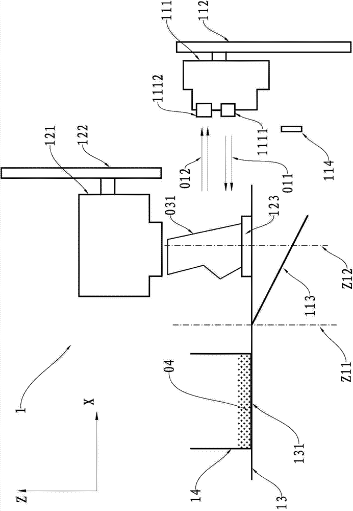
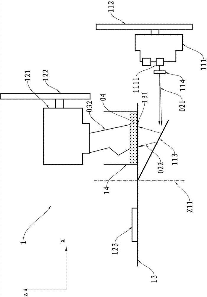
[0034] see figure 1The DLP three-dimensional printer 1 is composed of a frame, a control unit mounted on the frame, a scanning projection unit, a scanning and forming loading unit, a carrying table 13 and a forming tank 14 . The scanning projection unit is composed of a scanning projection device 111, a first lifting device 112, a light reflector 113, and a projection lens 114. The scanning projection device 111 is driven by the first lifting device 112 to move in the Z-axis direction relative to the carrier table 13; The loading unit is composed of a forming stage 121, a second elevating device 122 and a scanning object stage 123. The forming object stage 121 is driven by the second elevating device 122 to move in the Z-axis direction relative to the carrying platform 13; The table is arranged along the horizontal X-Y plane, and the relative frame can rotate around the rotation a...


PUM


Abstract

The invention relates to a DLP three-dimensional printer and a three-dimensional printing method based on a digital light processing technology and a three-dimensional scan technology, wherein the DLP three-dimensional printer comprises a frame, a control unit, a scanning and projecting unit, a scanning molding carrying unit as well as a molding groove mounted on the frame, wherein the molding groove is used for containing a light-cured resin solution; the scanning and projecting unit comprises a scanning light source, a molding light source, a digital micro-lens wafer and a scanning reflective light receiver; the scanning molding carrying unit is used for carrying a scanned object and molding a three-dimensional object in the molding groove; the digital micro-lens wafer is controlled by the control unit to process light generated by the scanning light source and the molding light source so as to correspondingly form scanning light for three-dimensional scanning on the object or molding light for curing the light-cured resin solution in the molding groove. According to the DLP three-dimensional printer, the processing capability of the digital micro-lens wafer on light can be fully utilized, so that the shape and the size of facula of the scanning light beam are no longer limited by the scanning light source.

Description

technical field [0001] The invention relates to a rapid prototyping device and a prototyping method thereof, in particular to a three-dimensional printer and a three-dimensional printing method based on digital light processing technology and three-dimensional scanning technology. Background technique [0002] A 3D printer is a device based on a digital model of a 3D object, using materials such as plastic, liquid photocurable resin, and powdered metal to construct a 3D object by layer-by-layer printing. [0003] Digital Light Processing (DLP for short) is a new type of projection technology based on a digital micromirror device (DMD for short, also known as a digital micro device). The digital micromirror chip is a semiconductor switch. 500,000 to 1.3 million microlenses are integrated on the CMOS silicon substrate, each microlens represents a pixel, when a microlens is in the "on" state, the incident light will be reflected and the image will be projected onto the screen t...

Claims


Application Information

Patent Timeline
Patent Type & Authority Applications(China)
IPC IPC(8): B29C67/00B22F3/115B33Y30/00B33Y40/00
Inventor 何永刚苏健强
Owner PRINT RITE UNICORN IMAGE PROD CO LTD
Learn More