High-flexibility deburring machine

A deburring machine, highly flexible technology, applied in the direction of grinding machine parts, machine tools suitable for grinding workpiece edges, metal processing equipment, etc. Complexity and other problems, to achieve the effect of reducing equipment cost, improving resource utilization efficiency, and improving flexibility

Active Publication Date: 2015-06-24
QINGDAO UNIV OF SCI & TECH
View PDF6 Cites 8 Cited by
  • Summary
  • Abstract
  • Description
  • Claims
  • Application Information

AI Technical Summary

Problems solved by technology

[0002] Most of the existing mechanical deburring devices use one-way buffering devices, such as radial buffering or axial buffering, which have certain flexibility, but as an important part of advanced manufacturing technology, it must be suitable for deburring of various parts. The compliance of the deburring device at the end of the manipulator does not meet the needs of complex situations, resulting in the manipulator, tool or parts being easily damaged, which has an adverse effect on the deburring operation. Therefore, it is necessary to take measures to improve the compliance of the mechanical deburring device sex
Existing mechanical deburring devices mostly use springs or air cylinders to achieve the soft function, which not only makes a lot of noise, but also requires additional air source equipment, and the structure is complex

Method used


Image

  • High-flexibility deburring machine
  • High-flexibility deburring machine
  • High-flexibility deburring machine

Examples


Embodiment Construction

[0014] The present invention will be described in detail below in conjunction with the accompanying drawings.

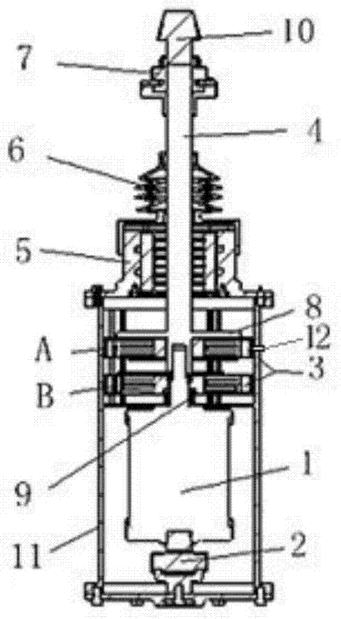
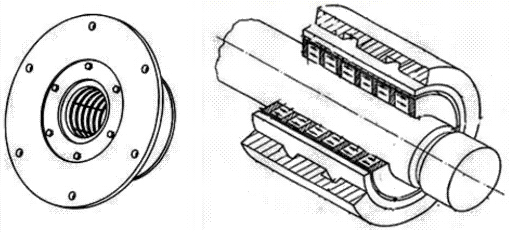
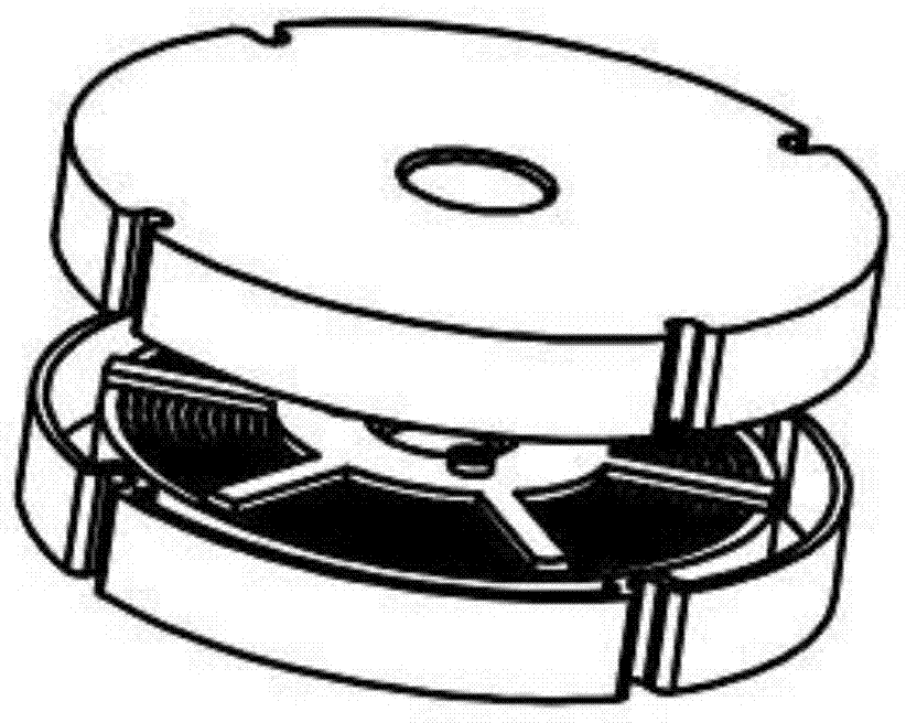
[0015] Such as figure 1 As shown, the present invention includes a motor 1, an axial buffer coil 3, a rotating shaft 4, an electromagnetic bearing 5 and a casing 11; the motor 1 and the axial buffer coil 3 are located in the casing 11, and the axial buffer coil 3 is composed of A Composed of two parts, A coil and the motor 1 are guaranteed through the bearing sleeve 9, and the farthest distance between the B coil and the A coil is constrained by the fixed circular plate 8 on the rotating shaft 4; the electromagnetic bearing 5 is located on the machine The outside of the casing 11 is fixedly connected to the casing 11; one end of the motor 1 is connected to the universal joint 2, the universal joint 2 is fixedly connected to the casing 11, the motor 1 is connected to the rotating shaft 4 through a spline, and the rotating shaft 4 is connected through a torque-limiting...


PUM


Abstract

The invention belongs to the field of machining, and particularly relates to a high-flexibility deburring machine arranged at the tail end of a mechanical arm. The high-flexibility deburring machine comprises a motor, an axial buffer coil, a rotating shaft, an electromagnet bearing and a machine shell; the motor and the axial buffer coil are located in the machine shell, and the electromagnet bearing is located on the outer side of the machine shell and is fixedly connected with the machine shell; one end of the motor is connected with a cardan joint which is fixedly connected with the machine shell; the motor is connected with the rotating shaft through a spline, and the rotating shaft is connected with a tool bit through a torque limiter coupling; a dustproof cover is arranged at the position, between the electromagnet bearing and the torque limiter coupling, on the outer side of the rotating shaft. According to the high-flexibility deburring machine, as the axial buffer coil and the electromagnet bearing serve as buffer devices, bothway buffering can be achieved, the one-way buffer function can be achieved, the flexibility is high, the smoothness of a mechanical deburring device is improved, and the deburring effect is good; the motor is directly adopted for driving, so that an air compressor is not needed for conversion, the cost is reduced, the resource using efficiency is improved, and the noise after driving is smaller.

Description

technical field [0001] The invention belongs to the field of mechanical processing, and in particular relates to a highly flexible deburring machine arranged at the end of a manipulator. Background technique [0002] Most of the existing mechanical deburring devices use one-way buffering devices, such as radial buffering or axial buffering, which have certain flexibility, but as an important part of advanced manufacturing technology, it must be suitable for deburring of various parts. The compliance of the deburring device at the end of the manipulator does not meet the needs of complex situations, resulting in the manipulator, tool or parts being easily damaged, which has an adverse effect on the deburring operation. Therefore, it is necessary to take measures to improve the compliance of the mechanical deburring device sex. Existing mechanical deburring devices mostly use springs or air cylinders to achieve the smoothing function, which not only makes a lot of noise, but ...

Claims


Application Information

Patent Timeline
Patent Type & Authority Applications(China)
IPC IPC(8): B24B41/04
CPCB24B9/00B24B41/002
Inventor 王宪伦崔玉霞喻洋
Owner QINGDAO UNIV OF SCI & TECH
Why Eureka
Try Eureka