PTC heating tube automatic glue spraying machine

A technology of automatic glue spraying machine and heating tube, which is applied in the direction of spraying device, etc., can solve the problems of lack of glue and deformation of PTC heating tube.

Active Publication Date: 2017-01-11
嘉善县魏塘资产管理有限公司
View PDF7 Cites 0 Cited by
  • Summary
  • Abstract
  • Description
  • Claims
  • Application Information

AI Technical Summary

Problems solved by technology

The invention patent scheme can objectively fulfill the technical effect recorded in paragraph 0007 of its specification, but it has no inspiration for the gluing of the PTC heating tube, because the electrode strip is solid and can withstand the corresponding pressure, while the PTC heating tube The wall thickness of the PTC heating tube is usually below 2 mm, or even below 1.5 mm (see paragraph 0019 of the aforementioned CN201499328U specification), and because the lumen of the PTC heating tube needs to be provided with the aforementioned PTC heating core, it is hollow, so if If it is glued by roller coating, that is, by contact, it will inevitably cause deformation

Method used


Image

  • PTC heating tube automatic glue spraying machine
  • PTC heating tube automatic glue spraying machine
  • PTC heating tube automatic glue spraying machine

Examples


Embodiment Construction

[0025] In order to enable examiners of the Patent Office, especially the public, to understand the technical essence and beneficial effects of the present invention more clearly, the applicant will describe in detail in the form of examples below, but the description of the examples is not intended to describe the solution of the present invention. As a limitation, any equivalent transformations made according to the concept of the present invention that are merely formal rather than substantive should be regarded as the technical solution scope of the present invention.

[0026] In the following description, all the concepts related to the directionality (or azimuth) of up, down, left, right, front and back are for the position state of the picture being described, and the purpose is to facilitate the public It is understood that it cannot be understood as a special limitation on the technical solution provided by the present invention.

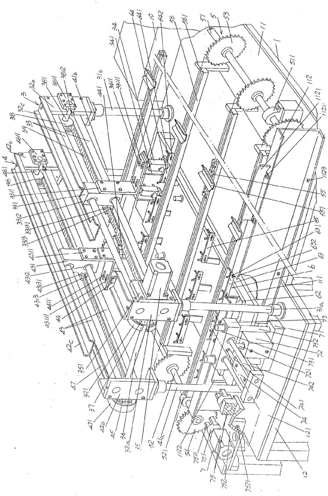
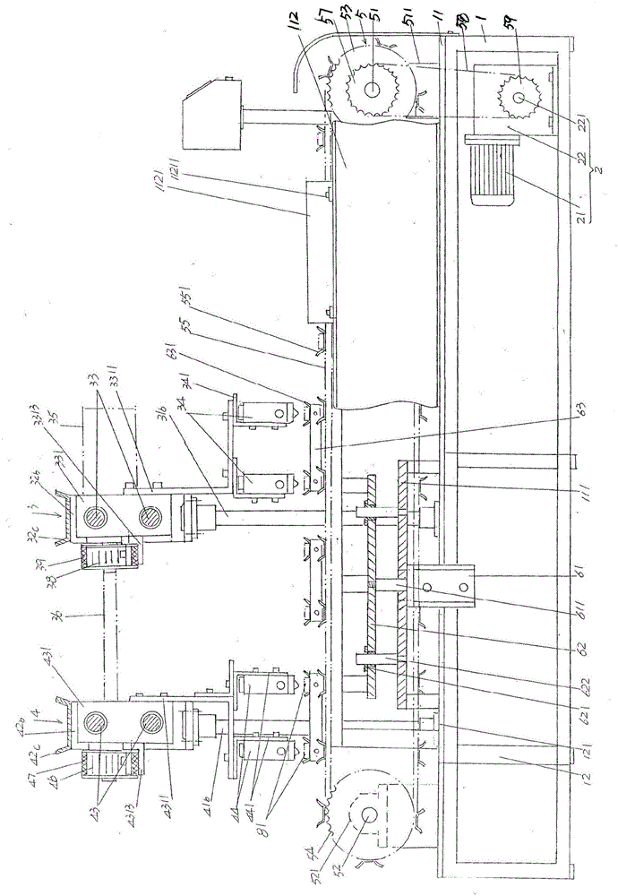
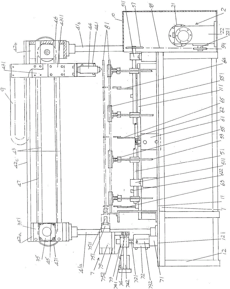
[0027] See figure 1 , A frame 1 is given. ...


PUM


Abstract

The invention relates to an automatic PTC heating tube glue spraying machine, and belongs to the technical field of devices special for manufacturing PTC heaters. The automatic PTC heating tube glue spraying machine comprises a rack provided with a table board plate on the upper portion, a power mechanism arranged accompanying with the rack, a PTC heating tube front face glue spraying mechanism, a PTC heating tube back face glue spraying mechanism, a PTC heating tube conveying mechanism arranged on the table board plate and connected with the power mechanism, a PTC heating tube lifting mechanism arranged at the left end of the table board plate, and a PTC heating tube turnover mechanism arranged at the front side or rear side of the left end of the table board plate, wherein the PTC heating tube front face glue spraying mechanism and the PTC heating tube back face glue spraying mechanism are connected in a transmission mode and arranged at the left end of the table board plate in the state of rising high above the table board plate, and the PTC heating tube front face glue spraying mechanism is located at the right side of the PTC heating tube back face glue spraying mechanism. The requirement for spraying glue on PTC heating tubes in a non-contact mode of the PTC heating tube front face glue spraying mechanism and the PTC heating tube back face glue spraying mechanism are met, lack of glue is avoided, the manpower investment is reduced, the gluing efficiency is high, and the automatic PTC heating tube glue spraying machine is environmentally friendly and convenient to manufacture, use and maintain.

Description

Technical field [0001] The invention belongs to the technical field of special devices for the manufacture of PTC heaters, and specifically relates to an automatic glue spraying machine for PTC heating pipes, which is used to spray adhesive on the surface of the PTC heating pipe facing the heat sink aluminum sheet, so that the heat sink aluminum sheet can be combined with the adhesive by the adhesive. The PTC heating tube is cemented. Background technique [0002] The aforementioned PTC heating tube is a component of the structural system of the PTC heating device (also called “PTC heater” in the industry, the same below). Specifically, the PTC heating device is mainly composed of the following four parts: one is the heating element, the The heating element is also called the heat sink; the second is the PTC heating core; the third is the tailstock; the fourth is the electrical connection support base. The heating element includes a PTC heating tube and a corrugated aluminum hea...

Claims


Application Information

Patent Timeline
Patent Type & Authority Patents(China)
IPC IPC(8): B05B13/02
Inventor 黄明峰
Owner 嘉善县魏塘资产管理有限公司
Why Eureka
Try Eureka