A hybrid excitation synchronous motor with built-in magnetic bridge combined rotor core

A hybrid excitation synchronous and rotor core technology, applied to synchronous motors with stationary armatures and rotating magnets, synchronous machines, magnetic circuit rotating parts, etc., can solve the problem of increasing the axial length and overall weight of the motor, and unfavorable motor efficiency and system efficiency, eddy current loss increase, etc., to reduce the risk of demagnetization, expand the magnetic field adjustment performance, reduce eddy current loss and rotor heating effects

Active Publication Date: 2017-10-31
NANJING UNIV OF AERONAUTICS & ASTRONAUTICS
View PDF5 Cites 0 Cited by
  • Summary
  • Abstract
  • Description
  • Claims
  • Application Information

AI Technical Summary

Problems solved by technology

However, in the structure of the traditional rotor magnetic shunt hybrid excitation synchronous motor, the axial extension of the rotor pole piece increases the axial length and overall weight of the motor, which limits its application in occasions with limited volume and weight.
And there is also the problem that the rotor is a monolithic structure instead of a laminated structure, resulting in increased eddy current loss, which is not conducive to the improvement of motor efficiency and system efficiency, and limits its application in occasions that require high efficiency

Method used


Image

  • A hybrid excitation synchronous motor with built-in magnetic bridge combined rotor core
  • A hybrid excitation synchronous motor with built-in magnetic bridge combined rotor core
  • A hybrid excitation synchronous motor with built-in magnetic bridge combined rotor core

Examples


Embodiment Construction

[0023] The present invention will be further described below in conjunction with the accompanying drawings.

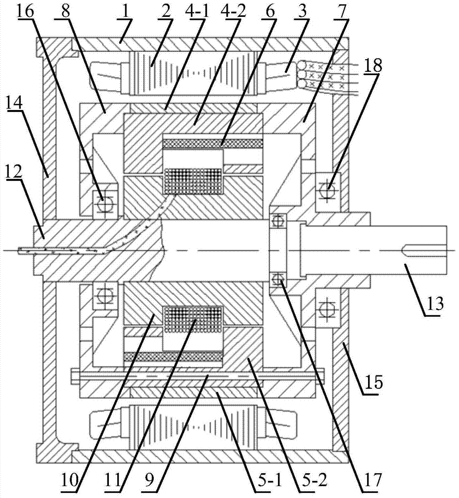
[0024] Such as figure 1 As shown, the present invention provides a combined rotor core hybrid excitation synchronous motor with a built-in magnetic bridge, including a casing 1 and a stator disposed in the casing 1, a rotor, a support shaft 12, and an annular guide fixed on the support shaft 12. The magnetic bridge 10 and the rotating shaft 13; the stator includes the stator core 2 and the armature winding 3 embedded in the stator slot; the stator core 2 is fixed on the casing 1 . The rotating shaft 13 is an output shaft and is arranged coaxially with the supporting shaft 12 .

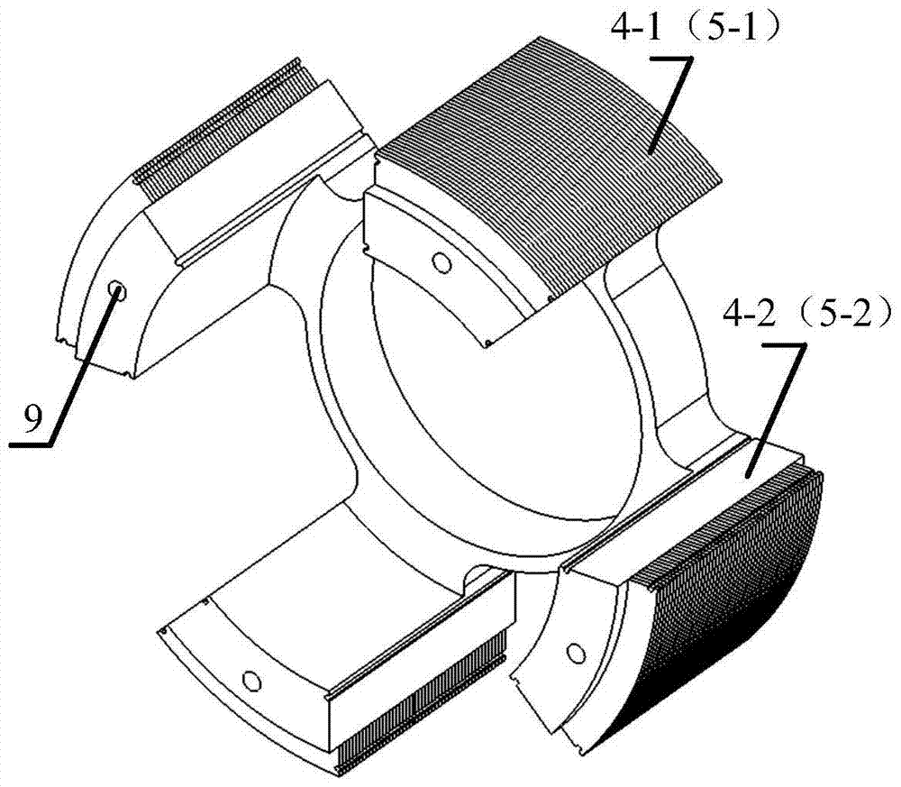
[0025] Denote the number of rotor pole pairs as p r , the rotor contains 2p r Block rotor core, 2p r The tangentially magnetized permanent magnets 6 , the front rotating bracket 7 , the rear rotating bracket 8 , and the interpole tie rods 9 with N poles and S poles interlacedly distributed ...


PUM


Abstract

The invention discloses a mixed excitation synchronous motor with combined rotor cores internally provided with retained magnetic bridges. The mixed excitation synchronous motor comprises a motor shell, a stator, a rotor, the annular retained magnetic bridges fixed to a supporting shaft and a rotating shaft, wherein the stator, the rotor, the annular retained magnetic bridges and the rotating shaft are arranged in the motor shell. The stator comprises a stator core and an armature winding embedded into a groove of the stator. The rotor comprises the two oppositely-closed combined rotor cores distributed in a staggered mode and a tangential magnetization permanent magnet. The portions, in contact with main air gaps, of the combined rotor cores are of lamination structures, and the other portions of the combined rotor cores are of complete-block structures. Exciting windings are embedded into the annular retained magnetic bridges, the annular retained magnetic bridges are located on the inner sides of the rotor cores, and additional air gaps exist between the annular retained magnetic bridges and the rotor cores. According to the mixed excitation synchronous motor, the space inside the rotor is sufficiently used on the basis that the capacity for adjusting the air gap magnetic field width range of the mixed excitation synchronous motor is kept, and the axial length and the weight of the motor can be reduced; the portions, in contact with the main air gaps, of the rotor cores are of the lamination structures, the eddy-current losses of the rotor are reduced, and the mixed excitation synchronous motor has the important application value in new energy automobiles and independent power systems.

Description

technical field [0001] The invention relates to a synchronous motor, in particular to a hybrid excitation synchronous motor. Background technique [0002] The hybrid excitation motor integrates the wide range adjustment of the air gap magnetic field of the electric excitation motor and the advantages of high power density and high efficiency of the permanent magnet motor. prospect. According to the interaction relationship between the permanent magnet magnetic potential and the electric excitation magnetic potential, the hybrid excitation motor can be divided into three types: the magnetic potential series excitation type, the shunt excitation type, and the mixed excitation type. [0003] The typical structure of the series excitation type is that the electric excitation winding is embedded and wound on the magnetic pole below the permanent magnet. Consumption increases. At the same time, the magnetomotive force of electric excitation acts directly on the permanent magnet...

Claims


Application Information

Patent Timeline
Patent Type & Authority Patents(China)
IPC IPC(8): H02K21/14H02K1/27
CPCH02K1/2773H02K21/022H02K21/025H02K21/14H02K2201/03
Inventor 张卓然戴冀蒋奎
Owner NANJING UNIV OF AERONAUTICS & ASTRONAUTICS
Why Eureka
Try Eureka