Magnetic shunt hybrid magnetic pole type synchronous motor

A hybrid magnetic pole, synchronous motor technology, applied in synchronous motors with static armatures and rotating magnets, etc., can solve problems such as axial magnetic path length, and achieve low magnetic leakage, wide adjustment range, and low coupling. Effect

Active Publication Date: 2016-09-07
NANJING UNIV OF AERONAUTICS & ASTRONAUTICS
View PDF6 Cites 0 Cited by
  • Summary
  • Abstract
  • Description
  • Claims
  • Application Information

AI Technical Summary

Problems solved by technology

[0004] Hybrid excitation motors, especially brushless excitation hybrid excitation synchronous motors, generally have a radial magnetic circuit and an axial magnetic circuit. The representative one is the rotor pole split hybrid excitation synchronous motor proposed by the British scholar E.Spooer. The electric excitation magnetic circuit passes through the stator casing, and the axial magnetic circuit is long; the other is the rotor magnetic shunt type hybrid excitation synchronous motor, and the axial magnetic circuit passes through the N-pole yoke extension body, the S-pole yoke extension body and the Magnetic bridge, simple structure, short axial magnetic circuit, easy to adjust the magnetic field, but the electric excitation and permanent magnet on the rotor are parallel magnetic circuits, and the electric excitation and permanent magnet interact with each other during the magnetic adjustment process

Method used


Image

  • Magnetic shunt hybrid magnetic pole type synchronous motor
  • Magnetic shunt hybrid magnetic pole type synchronous motor
  • Magnetic shunt hybrid magnetic pole type synchronous motor

Examples


Embodiment Construction

[0031] Below in conjunction with accompanying drawing, technical scheme of the present invention is described in further detail:

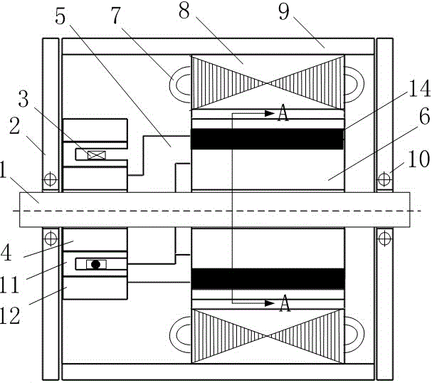
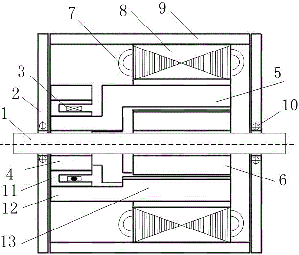
[0032] The present invention designs a magnetic shunt type hybrid magnetic pole type synchronous motor, such as figure 1 , figure 2 , including a casing 9 , a stator and a rotor arranged in the casing 9 , the stator includes a stator core 8 and an armature winding 7 , and the rotor includes a permanent magnet 14 . The stator core 8 is fixed on the casing.

[0033] The rotor includes a rotating shaft 1 and an annular electrically excited S pole shoe 4 and an annular electrically excited N pole shoe 12 arranged at one axial end of the rotating shaft 1; the annular electrically excited S pole Boot 4 is fixedly connected with rotating shaft 1.

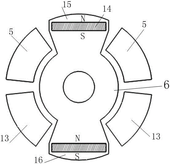
[0034] Such as Figure 4 As shown, an annular field winding support 11 is arranged between the electric excitation S pole shoe 4 and the electric excitation N pole shoe 12, and the excitation winding suppo...


PUM


Abstract

The invention discloses a magnetic shunt hybrid magnetic pole type synchronous motor, which comprises a casing, a stator and a rotor arranged in the casing. The electric excitation N pole on the rotor extends in the shape of a trumpet along one end of the axial direction, and gathers in the ring-shaped electric excitation N pole shoe; S pole pole boots. An excitation support for embedding an excitation winding is arranged between the ring-shaped N-pole shoe and the ring-shaped S-pole shoe. The axial magnetic circuit used for magnetic adjustment passes through the ring-shaped N-pole shoe, the excitation bracket, and the ring-shaped S-pole shoe instead of the end cover and the casing. The permanent magnet magnetic circuit and the electric excitation magnetic circuit of the present invention are independent of each other, neither a parallel magnetic circuit nor a series magnetic circuit, and at the same time, the risk of demagnetization is avoided. The invention adopts a brushless structure and has high reliability. In addition, the DC magnetic modulation method is adopted, the control is simple, and bidirectional excitation can be realized, and the air gap magnetic field adjustment range of the electric excitation magnetic pole is wide.

Description

technical field [0001] The invention relates to a permanent magnet motor, in particular to a magnetic shunt type mixed magnetic pole type synchronous motor, which belongs to the field of synchronous motors. Background technique [0002] With the improvement of performance and price reduction of permanent magnet materials, the use of permanent magnet materials in motors is becoming more and more extensive. Permanent magnet motors have the advantages of high power density, small size, light weight, high efficiency, brushless, and simple structure. All countries in the world have invested a lot of manpower and material resources, and many permanent magnet motors with new structures have appeared. The air-gap magnetic field of the main pole of the permanent magnet motor cannot be adjusted or is relatively difficult, but when the permanent magnet motor is used as a generator, the change of the armature current or the speed of the load caused by the load will cause the terminal v...

Claims


Application Information

Patent Timeline
Patent Type & Authority Patents(China)
IPC IPC(8): H02K21/14
Inventor 宁银行汤杰刘闯朱姝姝干兴业
Owner NANJING UNIV OF AERONAUTICS & ASTRONAUTICS
Why Eureka
Try Eureka