
Photoelectric comprehensive cable with irregular filling ropes

A technology of special-shaped filling rope and optoelectronic integrated cable, which is applied to power cables, communication cables, insulated cables, etc. including optical transmission elements, can solve problems such as affecting optical communication, expensive wrapping materials, and easily damaged cable cores.

Active Publication Date: 2015-06-17
河南圣源线缆有限公司
View PDF10 Cites 1 Cited by
  • Summary
  • Abstract
  • Description
  • Claims
  • Application Information

AI Technical Summary

Problems solved by technology

However, the existing photoelectric composite cables mainly have the following problems: (1) When the outer gap between the adjacent conductors is large, in order to make the composite cable round and round, the loose tube that accommodates the optical fiber also needs to be made into a large size. Increased cost; (2) The wire and the loose tube are twisted to form a cable core, and the outside of the cable core is wrapped with a yarn-like substance, which is easy to damage the loose tube, causing abnormal optical signal transmission, and when the temperature changes significantly, the wrapping The substance damages the loose tube, thereby affecting optical communication, and the dressing material itself is expensive; (3) It is not easy to remove the loose tube by twisting the wire and the loose tube, and the dressing material needs to be cut before taking it out. It is easy to damage the cable core, and it is not easy to restore; and it is very troublesome to take out the loose tube

Method used


Image

  • Photoelectric comprehensive cable with irregular filling ropes
  • Photoelectric comprehensive cable with irregular filling ropes
  • Photoelectric comprehensive cable with irregular filling ropes

Examples


Embodiment 1

[0039] Implementation example 1, implementation example 2, and implementation example 3 are embodiments of special-shaped filling ropes in the present invention; implementation example 4 and implementation example 5 are embodiments of photoelectric composite cables with special-shaped filling ropes in the present invention.

[0040] Implementation example 1

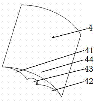
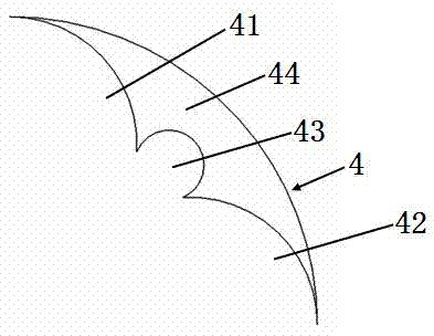
[0041] please see figure 1 figure 2 , optical cable or cable or photoelectric composite cable or photoelectric composite cable with a special-shaped filling rope, which includes a rope body 4, which is characterized in that the rope body is composed of four sections of cylindrical arcs, and the other end of the first cylindrical arc 41 is connected to the third cylinder One end of arc body 43, the other end of the third cylindrical arc body 43 connects one end of second cylindrical arc body 42, one end of fourth cylindrical arc body 44 connects one end of first cylindrical arc body 41, the fourth cylindrical arc bo...

Embodiment 2

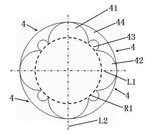
[0045] please see image 3 , and refer to figure 1 and figure 2 The special-shaped filling rope for optical cable or electric cable or photoelectric composite cable or photoelectric composite cable is characterized in that it is formed by splicing successively four small-structure filling rope bodies, and the four small-structure filling rope bodies are assembled into a complete cylinder body surface; the small structure filled rope body includes a rope body 4, and the rope body is composed of four sections of cylindrical arcs, the other end of the first cylindrical arc 41 is connected to one end of the third cylindrical arc 43, and the third cylindrical arc The other end of 43 connects one end of the second cylindrical arc body 42, one end of the fourth cylindrical arc body 44 connects one end of the first cylindrical arc body 41, and the other end of the fourth cylindrical arc body 44 connects the other end of the second cylindrical arc body 42 One end; the bending of the...

Embodiment 3

[0048] please see Figure 4 , and refer to Figure 1 to Figure 3 ; optical cable or electric cable or photoelectric composite cable or photoelectric composite cable with special-shaped filling rope, basically the same as implementation example 2, the difference is that it is formed by one extrusion molding of four small structure filling rope bodies, and the four small structure filling The rope body forms a complete cylinder surface; the small structure filled rope body includes a rope body 4, and the rope body is composed of four sections of cylindrical arcs, and the other end of the first cylindrical arc 41 is connected to the third cylindrical arc 43. One end, the other end of the third cylindrical arc body 43 is connected to one end of the second cylindrical arc body 42, one end of the fourth cylindrical arc body 44 is connected to one end of the first cylindrical arc body 41, and the other end of the fourth cylindrical arc body 44 is connected to the second cylindrical a...


PUM

PropertyMeasurementUnit
melt flow indexaaaaaaaaaa

Abstract

The invention belongs to the technical field of cables, and in particular relates to a photoelectric comprehensive cable with irregular filling ropes. The photoelectric comprehensive cable comprises a reinforcing part, a plurality of transmission conductors which are arranged at the outer side of the reinforcing part and are sequentially tangential to each other or arranged at small intervals, optical fiber communication units positioned in outer gaps between the adjacent transmission conductors, protecting layers for wrapping the transmission conductors and the optical fiber communication units, and protecting cover layers which wrap the protecting layers by extrusion molding. The photoelectric comprehensive cable is characterized in that the irregular filling ropes are arranged in the outer gaps between the adjacent transmission conductors; each optical fiber communication unit is clamped into the corresponding irregular filling rope. According to the photoelectric comprehensive cable with the irregular filling ropes, the irregular filling ropes are manufactured from special material; the photoelectric comprehensive cable has the beneficial technical effects of being simple in structure, low in cost, outstanding in performance, convenient to construct and the like.

Description

technical field [0001] The invention belongs to the technical field of cables, in particular to a photoelectric composite cable with special-shaped filling ropes. Background technique [0002] With the rapid development of the communication industry, the application of optical fiber cables and wires and cables is increasing. The use of photoelectric composite cables can make electricity and light directly enter the home, and operators do not need to apply for additional power loads. Therefore, they are more and more favored by operators. However, the existing photoelectric composite cable mainly has the following problems: (1) When the outer gap between the adjacent conductors is large, in order to make the composite cable round and round, the loose tube for containing the optical fiber also needs to be made into a large size. Increased cost; (2) The wire and the loose tube are stranded to form a cable core, and the outside of the cable core is wrapped with a yarn-like mat...

Claims


Application Information

Patent Timeline
Patent Type & Authority Applications(China)
IPC IPC(8): H01B9/00H01B7/18G02B6/44
CPCC08L23/12C08L2203/20C08L2203/202C08L2205/025C08L2205/035C08L2207/066G02B6/44G02B6/4407G02B6/4416G02B6/443G02B6/4432G02B6/4479H01B3/44H01B7/17H01B7/18H01B7/1895H01B7/24H01B7/28H01B7/2806H01B7/285H01B9/00H01B9/005H01B11/22H01B13/00H01B13/012C08L23/06C08L67/02C08L77/02C08K5/12C08K2003/2227C08L77/06C08K5/1345
Inventor 蒋菊生
Owner 河南圣源线缆有限公司
Learn More