


Quick Research
Generate reliable direction feasibility study reports for your R&D in just a few steps.

Technical Q&A
Discover and master advanced knowledge NOW. Basics, ideas, possibilities, all at once.

Find Solutions
As an expert in R&D theories, this can generate solutions to your technical problems instantly.

Evaluate Feasibility
Analyze your overall solution with one click, know your potential R&D risks in advance.

Monitor Landscape
Get weekly tech updates, stay abreast of the latest tech innovations and key insights.
Drying method for drying interior of gas bottle
A technology of gas cylinders and ovens, applied in drying, dryers, drying solid materials, etc., can solve the problems of poor drying speed and drying effect, increase drying cost, and reduce drying efficiency, so as to improve drying speed and drying efficiency. Drying efficiency, saving heat, and reducing labor costs
- Summary
- Abstract
- Description
- Claims
- Application Information
AI Technical Summary
Problems solved by technology
Method used
Image

Examples
Embodiment 1
[0049] Embodiment 1: as Figure 1 to Figure 4 As shown, a drying method for drying the inside of the gas cylinder, the drying method is to place the gas cylinder inside the oven, and use the oven to combine the internal heating method of heat convection with the external heating method of heat conduction. The combined heating method transfers the heating heat to the moisture inside the cylinder to dry the inside of the cylinder.
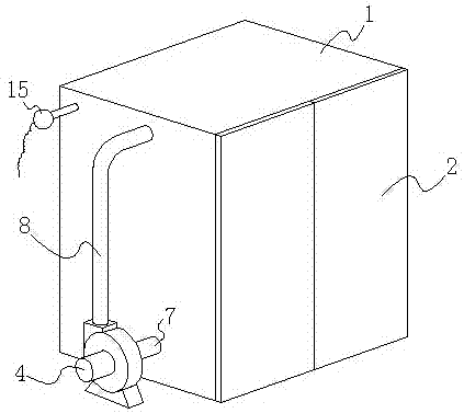
[0050] The oven includes a box body 1 and a box door 2 that is rotatably arranged on the side of the box body 1, and the gas cylinder 3 after the bottle valve is removed is moved into and placed inside the box body 1 with the bottle mouth facing upwards. The oven also includes a fan 4 located outside the box 1, a heating mechanism 5 arranged inside the box 1 for heating the inside of the box 1, and an air blower arranged inside the box 1. Mechanism 6; the blower 4 communicates with the inside of the box 1 through the air extraction pipe 7, and the b...
Embodiment 2
[0074] Embodiment 2: as Figure 8 and Figure 9 As shown, compared with Embodiment 1, the difference lies in that a pedal 18 is rotatably connected to the metal pallet 16 on the side close to the box door 2 . Due to the heavy weight of the gas cylinder, generally when moving the gas cylinder, the operator tilts the gas cylinder at a certain angle and then turns the cylinder to move the gas cylinder. In order to facilitate the movement of the gas cylinder, a Pedal, when moving the gas cylinder into or out of the oven, first open the door, then put down the pedal, move the gas cylinder into or out of the oven along the pedal, after moving in or out, put the pedal away, and close the door , so that the gas cylinder can be moved into or out of the oven very quickly, which further improves the drying efficiency.
Embodiment 3
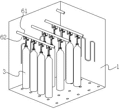
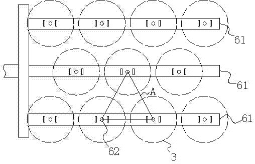
[0075] Embodiment 3: as Figure 10 and Figure 11 As shown, compared with Embodiment 1, the difference is: the number of the main blowing pipe 61 is provided with multiple roots, and each of the main blowing pipes 61 is provided with multiple links to each other with the main blowing pipe 61 The secondary blowing pipe 62 of pass. This increases the drying capacity in the oven and improves the drying efficiency.
[0076] The secondary blowing pipes 62 arranged on the plurality of main blowing pipes 61 are dislocated in the horizontal plane, as in this embodiment, the main blowing pipes are set to 3, and the first and last main blowing pipes There are 4 secondary air blowing pipes, and 3 secondary air blowing pipes 62 on the main air blowing pipe 61 in the middle. The spacing between two adjacent main blowing pipes 61 is equal, and the spacing between the secondary air outlet pipes 62 arranged on each main blowing pipe is also equal. Among the multiple secondary blowing pipes...
PUM
 Abstract
Description
Claims
Application Information
 - R&D Engineer
- R&D Manager
- IP Professional
- Industry Leading Data Capabilities
- Powerful AI technology
- Patent DNA Extraction
Browse by: Latest US Patents, China's latest patents, Technical Efficacy Thesaurus, Application Domain, Technology Topic, Popular Technical Reports.
© 2024 PatSnap. All rights reserved.Legal|Privacy policy|Modern Slavery Act Transparency Statement|Sitemap|About US| Contact US: help@patsnap.com