
Bi-directional seal low-flow-resistance stop valve

A two-way sealing, low flow resistance technology, used in lift valves, valve devices, engine components, etc., can solve the problems of high flow resistance, unsuitable for reverse sealing, high performance requirements of the actuator, and achieve low flow resistance. Effect

Active Publication Date: 2015-06-17
BEIJING AEROSPACE RATE MECHANICAL & ELECTRICAL ENG CO LTD +1
View PDF6 Cites 8 Cited by
  • Summary
  • Abstract
  • Description
  • Claims
  • Application Information

AI Technical Summary

Problems solved by technology

[0002] The main problem of the current stop valve is the high flow resistance, and it is not suitable for reverse sealing, especially for high-pressure stop valves. The sealing force is all derived from the actuator (except the reverse seal), and the performance requirements of the actuator are relatively high. , so a globe valve with low flow resistance and bi-directional sealing is required

Method used


Image

  • Bi-directional seal low-flow-resistance stop valve
  • Bi-directional seal low-flow-resistance stop valve
  • Bi-directional seal low-flow-resistance stop valve

Examples


Embodiment 1

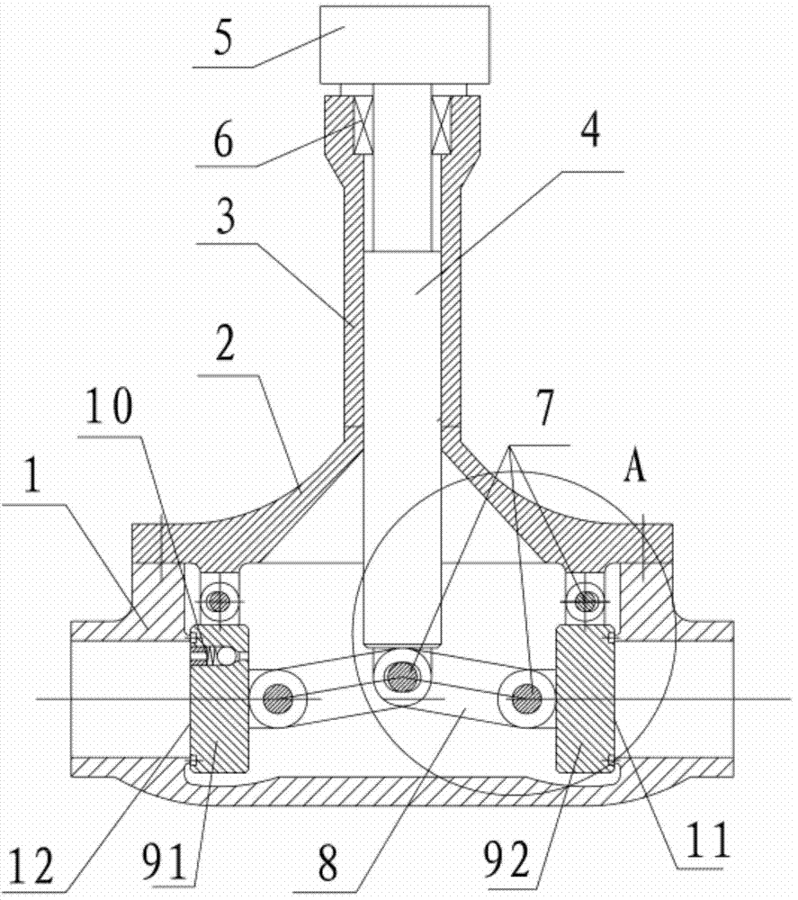
[0026] like figure 1 As shown, a two-way sealing low flow resistance cut-off valve includes a valve casing, a valve disc, a valve stem, and an actuator. There is a valve cavity in the valve casing, and the valve cavity has two ports of inlet and outlet. The inlet and outlet of the valve cavity Symmetrically opposite to each other, located on both sides of the valve cavity.

[0027] The valve casing includes a valve cover 2 and a valve body 1. The valve cover 2 is connected with the valve body 1 and encloses to form a valve cavity. The valve cover and the valve body are connected by flanges and bolts. The valve body 1 is provided with an inlet and outlet communicating with the valve chamber, the valve cover 2 is provided with a hollow valve neck 3 communicating with the valve chamber, and one end of the valve stem 4 passes through the valve neck 3 and enters the valve chamber.

[0028] One end of the valve stem 4 is connected with the actuator 5 located outside the valve chamb...

Embodiment 2

[0041] The difference between this embodiment and Embodiment 1 is that: image 3 , 4As shown, the lengths of the two connecting rods connecting the valve stem and the two discs are different. The central axis of the valve neck is closer to the opening of the valve cavity where the valve disc connected by the shorter connecting rod is located, and the central axis of the valve neck is farther away from the opening of the valve cavity. The port of the valve cavity matched by the disc connected by the connecting rod is far away, and when the valve stem moves, it is ensured that both discs can close the matching port of the valve cavity. That is, the connecting rod connecting the valve stem and the first valve disc 91 is longer than the connecting rod connecting the valve rod and the second valve disc 92, the first valve disc 91 cooperates with the outlet 12, the second valve disc 92 cooperates with the inlet 11, and the center of the valve neck The axis is farther from the outle...


PUM


Abstract

The invention provides a bi-directional seal low-flow-resistance stop valve. The stop valve comprises a valve casing, valve flaps, a valve rod and an executing mechanism; the valve casing is provided with a valve chamber, the valve chamber comprises two openings that are an inlet and an outlet, and the inlet and the outlet of the valve chamber are arranged relatively and are arranged at the two sides of the valve chamber respectively; the number of the valve flaps are two, and the valve flaps are arranged in the valve chamber of the valve casing; one end of the valve rod is connected with the executing mechanism which is arranged outside the valve chamber, the executing mechanism possesses a driving force, and the other end of the valve rod stretches into the valve chamber and is connected with the two valve flaps; the two valve flaps are matched with the inlet and the outlet of the valve chamber respectively to open or close the inlet or outlet of the valve chamber; when the two valve flaps open in a proper place, the flaps are located at the outside of a flow channel formed by the inlet and the outlet of the valve chamber. By the arrangement of the two valve flaps which are correspondingly matched with the inlet and the outlet of the valve chamber respectively, the block valve can be sealed bi-directionally; when the two valve flaps open in a proper place, the flaps are located at the outside of the flow channel formed by the inlet and the outlet of the valve chamber, and the flow of fluid cannot be blocked by the valve flaps, so that low flow resistance is realized.

Description

technical field [0001] The invention relates to a stop valve, in particular to a two-way sealing low flow resistance stop valve, which belongs to the field of valves. Background technique [0002] The main problem of the current stop valve is the high flow resistance, and it is not suitable for reverse sealing, especially for high-pressure stop valves. The sealing force is all derived from the actuator (except the reverse seal), and the performance requirements of the actuator are relatively high. , so a low flow resistance and bi-directional sealing stop valve is required. [0003] In view of this, the present invention is proposed. Contents of the invention [0004] The technical problem to be solved by the present invention is to overcome the deficiencies of the prior art, and provide a two-way sealing low flow resistance cut-off valve, which can realize low flow resistance and two-way sealing, so that the sealing reliability is better. [0005] In order to solve the ...

Claims


Application Information

Patent Timeline
IPC IPC(8): F16K1/18F16K1/36F16K1/32
CPCF16K1/18F16K1/32F16K1/36
Inventor 滕磊军任宏杰申靖施晓丽王惠颖李亚鹏于洋
Owner BEIJING AEROSPACE RATE MECHANICAL & ELECTRICAL ENG CO LTD
Learn More