Method for clamping square bar on three-jaw self-centering chuck

A self-centering chuck and clamping technology, which is applied in the field of clamping, can solve problems such as insufficient clamping stability, and achieve the effect of enhancing stability and increasing clamping force

Inactive Publication Date: 2015-06-17
铜陵市永生机电制造有限责任公司
View PDF5 Cites 0 Cited by
  • Summary
  • Abstract
  • Description
  • Claims
  • Application Information

AI Technical Summary

Problems solved by technology

[0003] The technical problem to be solved by the present invention is that when the existing three-jaw self-centering chuck clamps an irregularly shaped workpiece such as a square bar, the line contact between the jaws and the square bar leads to insufficient clamping stability. A method for mounting square rods on a three-jaw self-centering chuck

Method used


Image

  • Method for clamping square bar on three-jaw self-centering chuck

Examples


Embodiment Construction

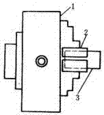
[0008] The present invention will be further described below in conjunction with the accompanying drawings.

[0009] Such as figure 1 As shown, the present invention includes the following steps: (1), select a hollow tube with an inner diameter slightly larger than the square rod and cut it along the longitudinal direction; (2), insert the square rod into the hollow tube; (3), insert the The hollow tube with the square rod is snapped onto the three-jaw self-centering chuck.

[0010] The hollow tube is preferably made of elastic material, so that when clamped by the claws, it can be further contracted due to the existence of the longitudinal seam so that the opposite rod can generate uniform pressure and strengthen the clamping force.

[0011] The present invention has been exemplarily described above in conjunction with the accompanying drawings. Obviously, the specific implementation of the present invention is not limited by the above methods, as long as various insubstanti...


PUM


Abstract

The invention discloses a method for clamping a square bar on a three-jaw self-centering chuck. The method comprises the following steps: (1) a hollow pipe with the inner diameter slightly greater than that of the square bar is selected, and a longitudinal joint of the hollow pipe is cut in the length direction; (2) the square bar is inserted into the hollow pipe; and (3) the hollow pipe inserted with the square bar is clamped on the three-jaw self-centering chuck. The method has the following beneficial effects: a regular hollow pipe fitting coats an irregular workpiece, so that the surface contact is realized between jaws and the hollow pipe, and the clamping stability is improved; and the longitudinal joint is arranged on the hollow pipe, and the inward uniform pressure can be generated to the square bar in clamping, so that the clamping force is enhanced.

Description

technical field [0001] The invention relates to a clamping method, in particular to a method for mounting clamping square rods on a three-jaw self-centering chuck. Background technique [0002] A chuck is a mechanical device used to clamp a workpiece on a machine tool. A machine tool accessory that clamps and positions workpieces by using the radial movement of movable jaws evenly distributed on the chuck body. The chuck is generally composed of three parts: the chuck body, the movable jaw and the jaw driving mechanism. The minimum diameter of the chuck body is 65 mm, and the maximum diameter is 1500 mm. There is a through hole in the center to pass the workpiece or bar; the back has a cylindrical or short tapered structure, which is connected directly or through a flange to the end of the machine tool spindle . Chucks are usually installed on lathes, cylindrical grinders and internal grinders, and can also be used with various indexing devices for milling machines and dr...

Claims


Application Information

Patent Timeline
Patent Type & Authority Applications(China)
IPC IPC(8): B23B31/12
CPCB23B31/12
Inventor 朱俊生
Owner 铜陵市永生机电制造有限责任公司
Why Eureka
Try Eureka