
Ring column cable net structure variable focal length reflective surface device

A technology of cable net structure and variable focal length, which is applied in the field of communication and electronics, can solve problems such as invariable focal length, and achieve the effects of simplifying the structure, improving utilization, and broadening the scope of functions and applications

Inactive Publication Date: 2017-06-16
XIDIAN UNIV
View PDF5 Cites 0 Cited by
  • Summary
  • Abstract
  • Description
  • Claims
  • Application Information

AI Technical Summary

Problems solved by technology

[0004] The purpose of the present invention is to overcome the defects in the above-mentioned prior art, and provide a variable focal length reflecting surface device with a ring column cable net structure, which is used to solve the technical problem that the focal length of the existing reflecting surface device is not variable, and broaden the scope of the reflecting surface device. functions and scope of application

Method used


Image

  • Ring column cable net structure variable focal length reflective surface device
  • Ring column cable net structure variable focal length reflective surface device
  • Ring column cable net structure variable focal length reflective surface device

Examples


Embodiment 1

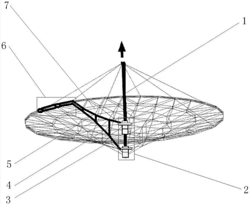
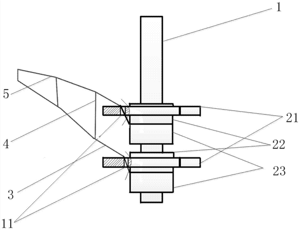
[0031] Refer to attached figure 1 , attached figure 2 And attached Figure 4, the present invention includes a central pillar 1, a sleeve set device 2, a fastening cable 3, an adjusting cable 4, a reflective cable 5, an expandable fixed truss unit 6 and a reflective mesh surface 7. Among them, the height of the central pillar 1 is 7.6m, the diameter of the outer diameter is 0.1m, and the truss structure of carbon fiber material is adopted; The cylinder 22 is composed of two lower moving sleeves 23, and the two upper moving sleeves 22 are located above the two lower moving sleeves 23, wherein the upper moving sleeve 22 is provided with a first flange 21, the first The flange 21 is provided with a first through hole 211; the expandable fixed truss unit 6 is composed of a connecting joint 62 and a folding rod 61, and a plurality of expandable fixed truss units 6 are connected to each other to form a foldable and unfoldable circular structure, It is used to support the reflect...

Embodiment 2

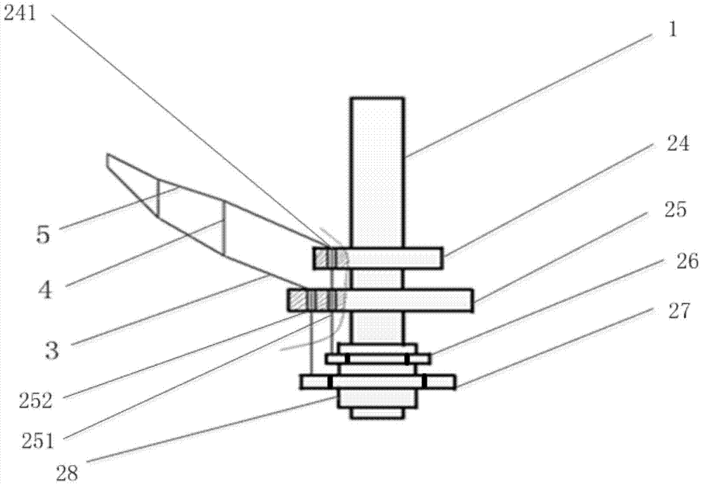
[0039] In the zoom structure schematic diagram of embodiment 2, except for the sleeve group device 2, the rest of the structure is the same as that of embodiment 1, and the differences are as follows:

[0040] Refer to attached image 3 , the sleeve group device 2 is composed of a small moving sleeve 24, a large moving sleeve 25 and a fixed sleeve 28; The cylinder 28 is fixed on the lower part of the central pillar 1; the small moving sleeve 24 is provided with a second via hole 241, and the large mobile sleeve 25 is provided with a third via hole 251 and a fourth via hole 252; the fixed sleeve 28 is provided with a The second flange 26 and the third flange 27; the second flange 26 and the third flange 27 all adopt aluminum alloy material, the size of the third flange 27 is greater than the second flange 26, the shape All be the hexagon of opening in the middle, on the position parallel with each limit of hexagon, be provided with the first through hole 211 of the multiple of...


PUM


Abstract

The invention discloses a variable focal length reflection surface device with a ring column cable net structure, which is used to solve the problem that the focal length of the existing reflection surface device is not variable. It includes a central pillar (1), a sleeve set device (2), a fastening cable (3), an adjusting cable (4), a reflection cable (5), an expandable fixed truss unit (6) and a reflection mesh surface (7). The sleeve set device (2) includes two moving sleeves sleeved on the center pillar (1), and the two moving sleeves move along the center pillar (1), driving the fastening cable (3) and the reflection cable (5) ) to generate a distance difference, and control to realize self-folding; at the same time, the reflective mesh surface (7) is folded to realize the mutual conversion between the parabolic surface and the plane of the reflective mesh surface (7), and the zoom operation of the reflective surface device is completed. The present invention can realize the mutual transformation of the shape of the reflective mesh surface (7) between the paraboloid and the plane, reflect or converge electromagnetic waves or light energy at different distances, and can be used in space or on the ground as a reflector or concentrator.

Description

technical field [0001] The invention belongs to the technical field of communication and electronics, and relates to a variable-focus reflection surface device with a ring-column cable-net structure, which can realize the convergence or reflection of electromagnetic energy or light energy between different distances, and is suitable for deployable antennas mounted on satellites or on the ground structure. Background technique [0002] Zoom technology is widely used in various fields. For example, in the camera lens in the optical system, the focal length can be appropriately changed by rotating the focus ring of the lens to realize the change of the focusing distance, so as to complete clear shooting of objects at different distances. [0003] However, in the reflector system commonly used in the field of communication and electronic technology, there are many difficulties in the application of zoom technology. The specific reasons can be summarized as follows: for small-siz...

Claims


Application Information

Patent Timeline
Patent Type & Authority Patents(China)
IPC IPC(8): H01Q15/14H01Q15/16
Inventor 郑飞陈梅温建荣
Owner XIDIAN UNIV
Learn More