Elevator emergency brake

An emergency braking and elevator technology, applied in the directions of transportation, packaging, elevators, etc., can solve the problems of inability to transmit the braking force, damage to the elastic body fixing bolts, etc., and achieve the effect of improving safety and simple structure.

Active Publication Date: 2017-04-12
HITACHI LTD
View PDF1 Cites 0 Cited by
  • Summary
  • Abstract
  • Description
  • Claims
  • Application Information

AI Technical Summary

Problems solved by technology

However, in the above-mentioned Patent Document 1, when the braking test is performed many times, the elastic body slides in the horizontal direction that is not restrained, that is, rearward as the braking is performed, so that the installation position and stability of the above-mentioned components are not correct. Changes, in the worst case, can lead to damage to the elastic body fixing bolts due to bending, there is a problem that the braking force obtained by the brake piece clamping the guide rail cannot be transmitted to the elastic body

Method used


Image

  • Elevator emergency brake
  • Elevator emergency brake
  • Elevator emergency brake

Examples


no. 1 example

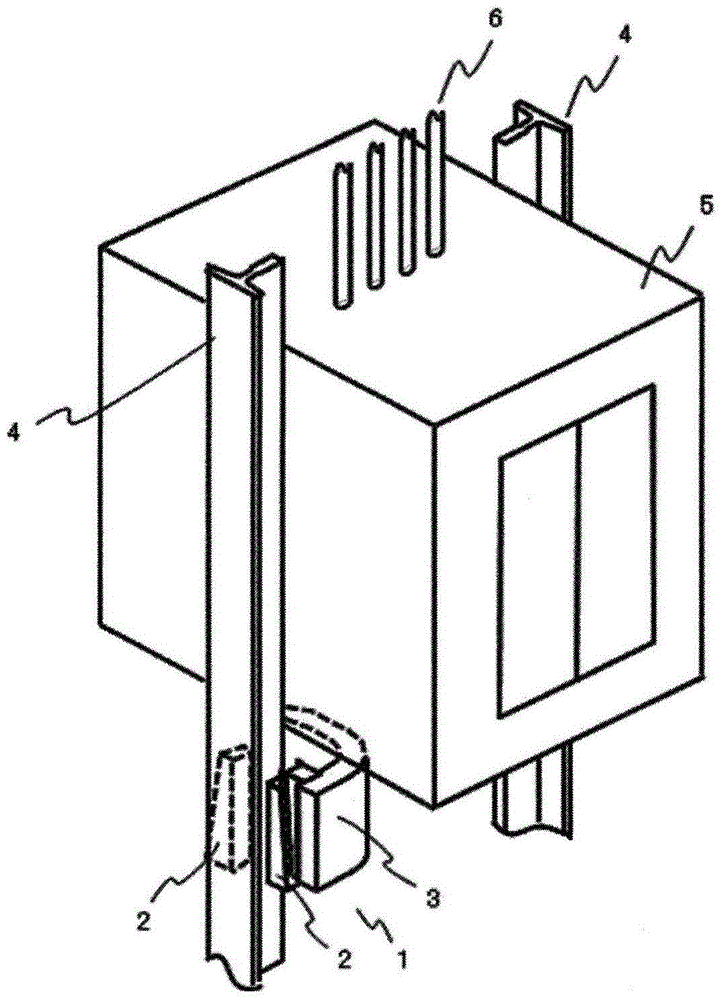
[0047] figure 1 It is a perspective view which shows the elevator installation which concerns on one Embodiment of this invention. An elevator body 5 serving as an elevator car on which passengers ride is connected to a drive system (not shown) located on the uppermost floor of a building via a rope 6 . Guide rails 4 for guiding the lifting body 5 to go up and down are arranged on both sides of the lifting passage. The emergency brake device 1 is provided at the lower end of the lifting body 5 so as to sandwich the guide rail 4 . An emergency brake device 1 (not shown) is also provided on the guide rail 4 on the opposite side, not shown, and both are connected by a connecting mechanism not shown. It should be noted that, in figure 1 Detailed structures such as elevator door operators and outer frames are omitted. and, in figure 1 The detailed structure of the frame of the emergency braking device 1 and the like are also omitted in the figure. In the emergency braking ...

no. 2 example

[0058] Next, another embodiment of the present invention will be described. The basic structure of the emergency braking device of this embodiment is basically the same as that of the first embodiment. The same structural parts as those of the first embodiment are given the same reference numerals, and descriptions thereof are omitted. Hereinafter, differences from the first embodiment will be described.

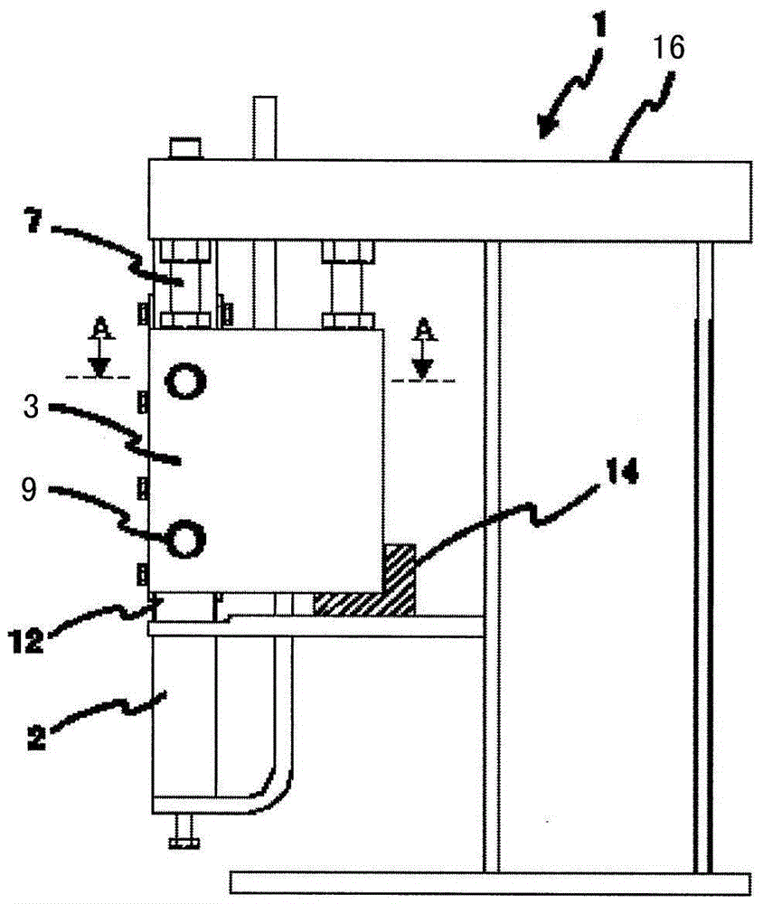
[0059] Figure 5 It is a side view showing the elastic body fixing structure of the emergency brake device according to another embodiment of the present invention. Such as Figure 5 As shown, the length of the back stopper of the emergency braking device in this embodiment is equal to the distance between the frame body 16 and the elastic body 3 , and is composed of bolts 13 fixed on the frame body 16 . Make this bolt 13 pass the hole that is arranged on the one side opposite to the back of elastic body 3 of frame body 16, and this bolt 13 is fastened and fixed on one s...


PUM


Abstract

The invention provides an emergency braking device of an elevator. When multiple braking tests are performed, the device can ensure proper braking force with reproducibility by a simple structure, so as to improve security. The emergency braking device of an elevator clamps an elevating guide rail of an elevating body when speed of the elevating body in an elevating channel exceeds a specified speed. The emergency braking device is characterized in that the device comprises a braking element which clamps and maintains the guide rail, a U-shaped elastic body which presses the braking element towards the guide rail, and a frame which stores the braking element and the U-shaped elastic body inside. The emergency braking device is also provided with a back surface stop block. When the braking element clamps and maintains the guide rail, the back surface stop block restrains the U-shaped elastic body from moving towards a direction far away from the guide rail which is clamped by the braking element.

Description

technical field [0001] The invention relates to an improvement of an emergency braking device of an elevator. Background technique [0002] An emergency braking device as a safety device is provided in existing elevator equipment, and when the descending speed of the lifting body reaches a constant speed or more, the emergency braking device makes the lifting body emergency stop with an appropriate deceleration. The emergency braking device is configured such that when the speed of the lifting body reaches a predetermined speed or more, the brake piece provided with two trapezoidal friction members clamps and holds the guide rail provided on the wall of the lifting passage, so that the elastic body opens, The braking force is generated by the force generated when the elastic body elastically deforms. The braking force varies with different elevator specifications. Generally speaking, the faster the elevator equipment is, the greater the mass, the greater the braking force r...

Claims


Application Information

Patent Timeline
Patent Type & Authority Patents(China)
IPC IPC(8): B66B5/16
CPCB66B5/18
Inventor 大森贡
Owner HITACHI LTD
Why Eureka
Try Eureka