
Control method of pneumatic conveying device

A technology of pneumatic conveying and control method, which is applied in the field of device control, can solve the problems that the accuracy of powder output from the powder feeder cannot be guaranteed, and the detection of powdery materials or powder concentration fails to attract enough attention, so as to achieve a good conveying effect. Effect

Active Publication Date: 2015-11-25
安徽天元塑业有限公司
View PDF8 Cites 0 Cited by
  • Summary
  • Abstract
  • Description
  • Claims
  • Application Information

AI Technical Summary

Problems solved by technology

The transmission of powder in the pipeline may be stagnant and blown away alternately. Therefore, the accuracy of the powder output by the powder feeder cannot guarantee the stability of the powder output at the outlet of the pipeline after being transported through the pipeline. For stable transmission, it is necessary to detect the state of powder transmission in key parts of the pipeline
[0005] Studies have shown that in the field of pneumatic conveying technology, powder concentration has a very important influence on the formed gas phase. At present, pneumatic conveying devices mainly focus on how to solve the technical problems mentioned above, but for the conveying object, that is, powdery materials or powder Concentration detection also failed to attract enough attention

Method used


Image

  • Control method of pneumatic conveying device

Examples


Embodiment Construction

[0018] The specific implementation manners of the present invention will be briefly described below in conjunction with the accompanying drawings.

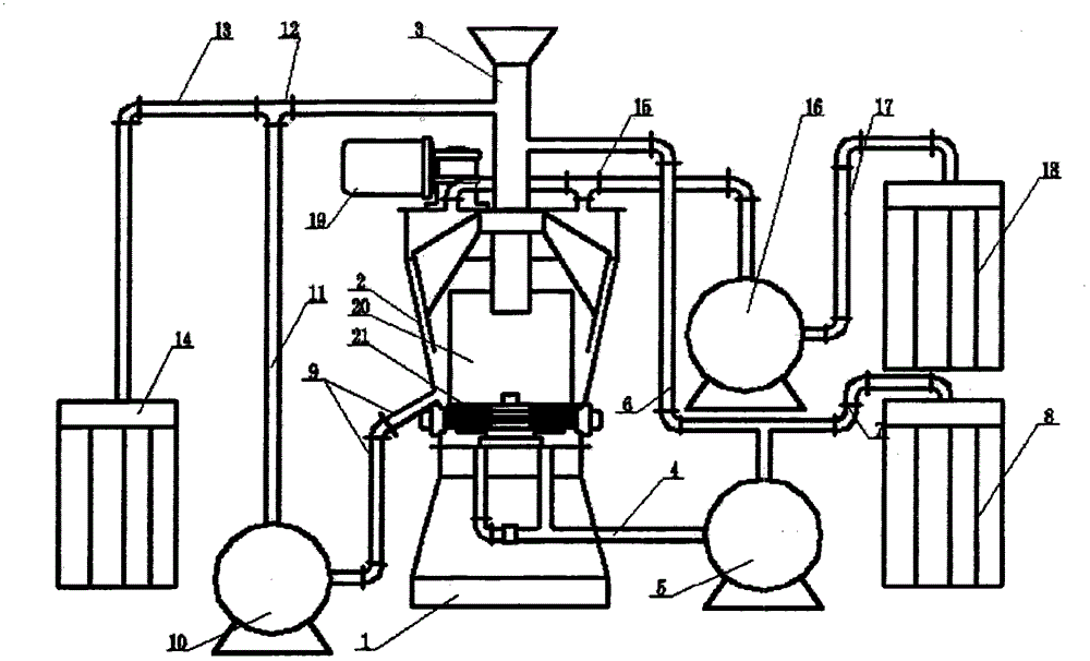
[0019] A pneumatic conveying device, comprising a base 1, a silo 2, a material inlet 3, a discharge pipe 4, a No. 1 fan 5, a feed pipe 6, a collection pipe 7, a collection device 8, a discharge Pipe two 9, No. two fan 10, pipeline 11, feed pipe two 12, collection pipe two 13, material collector two 14, discharge pipe three 15, No. three fan 16, collection pipe three 17, aggregate Device three 18, scraper system 19, filter screen 20, cutter wheel 21, wherein the feed bin 2 is installed on the base 1, the upper part of the feed bin 2 is provided with a feed port 3, and the inside of the feed bin 2 is provided with a filter screen 20, A cutter wheel 21 is installed at the bottom of the silo 2, and the cutter wheel 21 further crushes the unbroken bulk material. Above, the scraper system 19 is arranged on the outside of the silo 2, an...


PUM


Abstract

The invention relates to a control method for a pneumatic conveyor. The control method comprises the following steps: a, setting the stated powder concentration value range and the spindle alarm temperature of a tool wheel spindle motor on the input panel of an electric control unit; b, operating an electric device to start the pneumatic conveyor, collecting the relative signals by a concentration detecting device and a temperature sensor and transmitting the signals to a industrial personal computer of the electric control unit; c, wherein the industrial personal computer of the electric control unit comprises a judging unit, and performing the following judgment: while the spindle temperature is under the spindle alarm temperature, detecting the powder concentration; while the spindle temperature exceeds the spindle alarm temperature, warning by the electric control unit and stopping the machine. The control method for the pneumatic conveyor is capable of reducing the number of collecting blowers, improving the working efficiency of the pneumatic conveyor, and enhancing the automation degree of the machine.

Description

technical field [0001] The invention relates to the technical field of pneumatic conveying, and more specifically, the present invention relates to a control method for a device for pneumatically conveying materials. Background technique [0002] Pneumatic conveying device, also known as pneumatic lifting system, is a device that uses the energy of air to continuously convey and lift powdery bulk materials (cement, fly ash, slag powder, clinker, etc.). Traditional mechanical lifting equipment has the advantages of large lifting capacity, rich types of lifting, and high lifting height, and is widely used in various industries in today's society. However, it also has many disadvantages that cannot be underestimated. The price of the equipment is high, the one-time investment is large, the amount of maintenance is large, it is difficult to operate, the weight of the equipment is large, the investment in civil engineering is large, the area is large, and it is restricted by site...

Claims


Application Information

Patent Timeline
Patent Type & Authority Patents(China)
IPC IPC(8): B65G53/66
Inventor 吴联凯
Owner 安徽天元塑业有限公司
Learn More