
Construction Method of Welding and Positioning Device for Large Ladle Hanging Shaft

A welding positioning and construction method technology, applied in the direction of auxiliary equipment, welding equipment, auxiliary welding equipment, etc., can solve the problems of wasting materials, labor and time, etc., and achieve the effect of simplifying the process, simple operation and saving materials

Active Publication Date: 2016-08-24
FUJIAN XINGHANG MECHANICAL CASTING
View PDF7 Cites 0 Cited by
  • Summary
  • Abstract
  • Description
  • Claims
  • Application Information

AI Technical Summary

Problems solved by technology

[0002] For the hoisting and dumping of ladle tanks, the suspension shaft is an indispensable restriction. During installation, the suspension shafts on both sides of the ladle tank have strict requirements on the installation coaxial error, and large ladles are not suitable for finishing with machining centers due to their large volume. Positioning, in the prior art, the suspension shaft and the ladle are usually cast as one, and the part of the suspension shaft located in the ladle tank is cut off in the subsequent processing. This method not only wastes a lot of material, but also needs to be processed and cut The part of the hanging shaft is labor-intensive and time-consuming

Method used


Image

  • Construction Method of Welding and Positioning Device for Large Ladle Hanging Shaft
  • Construction Method of Welding and Positioning Device for Large Ladle Hanging Shaft

Examples


Embodiment Construction

[0013] The present invention will be further described below in conjunction with the accompanying drawings and specific embodiments.

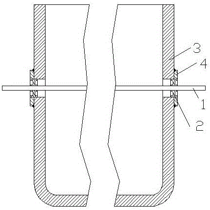
[0014] Such as Figure 1~2 As shown, the solution adopted by the present invention to solve the technical problem is that the solution adopted by the present invention is a welding positioning device for a large ladle hanging shaft, which includes a long positioning shaft 1 and two positioning circles of the same size Disk 2, the cylindricity error of the peripheral side of the long positioning shaft 1 is not greater than 0.05mm, the positioning disc 2 is coaxial with the long positioning shaft 1, and the coaxiality error between the positioning disc 2 and the long positioning shaft 1 is not greater than 0.03mm, two positioning discs 2 are relatively parallel and detachably sleeved on the long positioning shaft 1 .

[0015] In this embodiment, in order to prevent the long positioning shaft 1 from rusting and improve the service life, the long ...


PUM


Abstract

The invention relates to a large ladle hanging shaft welding positioning device and a construction method thereof. The large ladle hanging shaft welding positioning device comprises a long positioning shaft and two positioning disks with the same size, wherein the cylindrical form error of the circumferential side of the long positioning shaft is not greater than 0.05mm; the positioning disks are coaxial with the long positioning shaft; the coaxial error of the positioning disks and the long positioning shaft is not greater than 0.03mm; the two positioning disks are relatively parallel and are detachably arranged on the long positioning shaft in a sleeving way. Compared with the prior art, the large ladle hanging shaft welding positioning device has the benefits that the operation is simple, and a ladle tank hanging shaft can be accurately positioned and packaged. Compared with the conventional method for integrating a hanging shaft and a ladle tank, the construction method has the advantages that materials are greatly saved, the working procedure is simplified, and both labor and time are saved.

Description

technical field [0001] The invention relates to a large ladle hanging shaft welding positioning device and a construction method thereof. Background technique [0002] For the hoisting and dumping of ladle tanks, the suspension shaft is an indispensable restriction. During installation, the suspension shafts on both sides of the ladle tank have strict requirements on the installation coaxial error, and large ladles are not suitable for finishing with machining centers due to their large volume. Positioning, in the prior art, the suspension shaft and the ladle are usually cast as one, and the part of the suspension shaft located in the ladle tank is cut off in the subsequent processing. This method not only wastes a lot of material, but also needs to be processed and cut That part of the hanging shaft is labor-intensive and time-consuming. Contents of the invention [0003] The object of the present invention is to provide a large-scale ladle hanging shaft welding position...

Claims


Application Information

Patent Timeline
Patent Type & Authority Patents(China)
IPC IPC(8): B23K37/04
CPCB23K37/04
Inventor 李章新陈忠振陈忠霆郑建斌张小华张志清张祥
Owner FUJIAN XINGHANG MECHANICAL CASTING
Learn More