
Positioning device for distal locking of intramedullary nail

A positioning device and distal lock technology, applied in the direction of internal fixator, fixator, internal bone synthesis, etc., can solve the problems of aiming misalignment, induction failure, increasing iatrogenic trauma, etc.

Inactive Publication Date: 2015-06-10
安徽埃克索医疗机器人有限公司
View PDF11 Cites 10 Cited by
  • Summary
  • Abstract
  • Description
  • Claims
  • Application Information

AI Technical Summary

Problems solved by technology

When using the electronic navigation type intramedullary nail distal aiming device, the magnetic positioning method needs to make an incision at the distal keyhole, and use the detector to find the distal keyhole, which increases additional iatrogenic trauma, and because the probe The needle magnetic block is small, and the induction will fail when the deformation is large, so it is easy to cause misalignment

Method used


Image

  • Positioning device for distal locking of intramedullary nail
  • Positioning device for distal locking of intramedullary nail
  • Positioning device for distal locking of intramedullary nail

Examples


Embodiment Construction

[0052] Specific embodiments of the present invention will be described below in conjunction with the accompanying drawings.

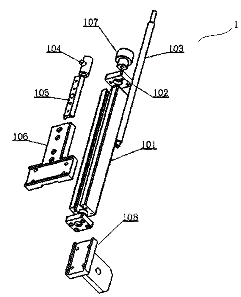
[0053] refer to Figure 1 to Figure 6 An embodiment of the positioning device for the locking nail at the distal end of the intramedullary nail of the present invention is shown, which includes a positioning mechanism 5 and an adjusting mechanism. Wherein, the positioning mechanism 5 is used for positioning the guide pin to be inserted into the lock hole at the distal end. Specifically, the locating mechanism 5 has a first locating ring 505 and a second locating ring 506 through which the guide needle passes sequentially for positioning. The first locating ring 505 and the second locating ring 506 are spaced from each other and concentrically arranged. Thus, when the center of circle of the first locating ring 505 and the center of circle of the second locating ring 506 are aligned with the center of circle of the distal locking hole, the first locatin...


PUM


Abstract

The invention relates to a positioning device for distal locking of an intramedullary nail. The positioning device comprises a positioning mechanism and an adjusting mechanism, wherein the positioning mechanism comprises a first positioning ring and a second positioning ring which are arranged at intervals and are concentrically arranged; a guide needle penetrates through the first positioning ring and the second positioning ring in sequence and is positioned by the first positioning ring and the second positioning ring; the adjusting mechanism comprises a longitudinal rotation assembly used for rotating around a longitudinal axis so as to drive the positioning mechanism to rotate around the longitudinal axis, a transverse rotation assembly used for rotating around a transverse axis so as to drive the positioning mechanism to rotate around the transverse axis, a longitudinal translational component used for driving the positioning mechanism to move along the longitudinal direction and a transverse translational component used for driving the positioning mechanism to move along the transverse direction; the positioning mechanism is detachably or fixedly connected to at least one of the four components; an intersection of the longitudinal axis and the transverse axis is arranged on a connection line of a circle center of the first positioning ring and a circle center of the second positioning ring; an included angle is formed between the plane formed by the longitudinal direction and the transverse direction and the penetrating path of the guide needle. The positioning device is capable of assisting a doctor to quickly and accurately positioning far-end lock holes under the conditions without extra iatrogenic wounds and low radiation frequency.

Description

technical field [0001] The invention relates to a surgical instrument, in particular to a positioning device for locking nails at the distal end of intramedullary nails. Background technique [0002] Intramedullary nailing is a commonly used internal fixation device for the treatment of femoral shaft fractures. During the operation, the femoral intramedullary nail is implanted from the medial pyriform sinus of the greater trochanter, the intramedullary nail is inserted into the bone marrow cavity, and the proximal and distal ends of the intramedullary nail are placed with locking nails. The intramedullary nails are fixed together to control the rotation of the fracture end and increase the firmness of the fixation. Intramedullary nail internal fixation is a closed minimally invasive surgery with a low rate of surgical infection, minimal damage to periosteal blood supply, and a low incidence of refracture. However, because the bone medullary cavity has an inward or outward ...

Claims


Application Information

Patent Timeline
IPC IPC(8): A61B17/90A61B17/72
CPCA61B17/7233A61B17/88A61B17/90
Inventor 唐佩福胡磊张立海郭娜卞庆武
Owner 安徽埃克索医疗机器人有限公司
Learn More