Outer rotor regulation type eddy current speed controller

An outer rotor and speed governor technology, which is applied to electrical components, electromechanical devices, electromechanical transmission devices, etc., can solve the problems of complex structure of the inner rotor adjustment mechanism, increase the difficulty and difficulty of processing, etc. The effect of maintenance and product economy

Inactive Publication Date: 2015-06-03
HOHAI UNIV
View PDF6 Cites 8 Cited by
  • Summary
  • Abstract
  • Description
  • Claims
  • Application Information

AI Technical Summary

Problems solved by technology

However, after the assembly of the outer rotor is completed, the adjustment of the inner rotor becomes very difficult due to the complex structure of the inner rotor adjustment mechanism and its location in the closed space enclosed by the outer rotor.
In addition, the complex inner rotor structure also greatly increases the difficulty of processing

Method used


Image

  • Outer rotor regulation type eddy current speed controller
  • Outer rotor regulation type eddy current speed controller
  • Outer rotor regulation type eddy current speed controller

Examples


Embodiment 1

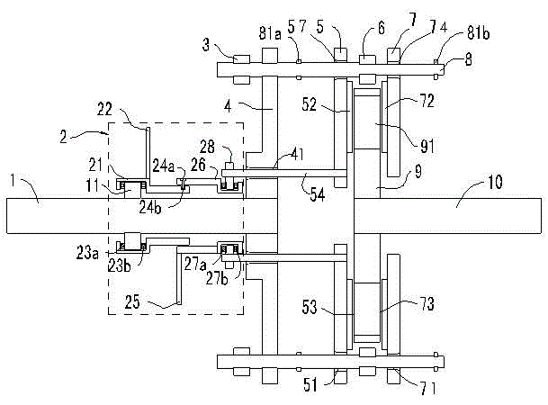
[0041] Such as figure 1 As shown, a vortex speed governor with external rotor adjustment includes an inner rotor and an outer rotor coaxially arranged.

[0042] The inner rotor includes an inner rotor shaft 10 and an inner rotor rotating disk 9 . Wherein, the inner rotor rotating disk 9 is coaxially and fixedly fitted on the outer periphery of the inner rotor shaft 10 .

[0043] Such as Figure 9 As shown, the inner rotor rotating disk 9 is uniformly provided with several through holes 93 along the circumferential direction, preferably eight through holes 93 . The shape of each through hole 93 is preferably a small rectangle, and a group of square permanent magnets 91 are nested in each through hole 93 .

[0044] The outer rotor includes an outer rotor shaft 1, two outer rotor moving discs and a rotary linear adjustment mechanism. Wherein, the outer rotor shaft 1 and the two outer rotor moving disks are coaxially arranged with the inner rotor shaft 10 .

[0045] The t...

Embodiment 2

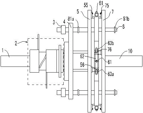
[0090] The structure and principle of embodiment 2 are basically the same as embodiment 1, the difference is: as Figure 10 As shown, the inner surface of the fixing sleeve 21 is connected with the axial fixing disk 11 through the first bevel bearing 29a. The linear rotation sleeve 26 and the connection plate 28 are connected through a second angled bearing 29b.

[0091] Additionally, if Figure 11 As shown, the inner rotor rotating disk 9 is uniformly provided with several through holes 93 along the circumferential direction, preferably eight through holes 93 . The shape of each through hole 93 is trapezoidal, and a group of trapezoidal disc planar windings 92 are nested in each through hole 93 .


PUM


Abstract

The invention discloses an outer rotor regulation type eddy current speed controller. The outer rotor regulation type eddy current speed controller comprises an inner rotor and an outer rotor, wherein the inner rotor comprises an inner rotor rotation disc in which a plurality of groups of permanent magnets are embedded; the outer rotor comprises two outer rotor motion discs which are symmetrically arranged at two sides of the inner rotor rotation disc, and a rotation liner regulating mechanism; each outer rotor motion disc is provided with a conducting metal disc; a variable gas gap is formed between each conducting metal disc and the corresponding inner rotor rotation disc; the rotation linear regulating mechanism, on one hand, enables each conducting metal disc to rotate synchronously together with the outer rotor, and on the other hand, enables the two variable gas gaps to change axially at the opposite directions or the same direction. After the structure is adopted, only one inner rotor rotation disc comprising the permanent magnets is required, so that the magnetic connection of the inner rotor and the outer rotor can be realized; the inner rotor is simple in structure, is low in processing difficulty, and is convenient for assembling and overhauling; two magnetic poles of each permanent magnet in the inner rotor rotation disc can be used at the same time, so that the permanent magnetic utilization ratio is high, the cost is reduced, and the product is economic.

Description

technical field [0001] The invention relates to a speed governor, in particular to an outer rotor regulating vortex speed governor. Background technique [0002] The existing permanent magnet eddy current speed regulating device is mainly composed of two parts: a permanent magnet rotor and a copper (or other conductor) rotor. Generally, the shaft of the motor and the shaft of the working machine are respectively connected to one of the rotors. There is an air gap (called an air gap) between the copper rotor and the permanent magnet rotor, and there is no mechanical connection for torque transmission. In this way, a soft (magnetic) connection is formed between the motor and the working machine, and the shaft torque and speed of the working machine can be changed by adjusting the air gap, so it can adapt to various harsh environments, and because there is no direct mechanical connection, the mechanical loss. [0003] However, in the existing structures, without exception, th...

Claims


Application Information

Patent Timeline
Patent Type & Authority Applications(China)
IPC IPC(8): H02K51/00
Inventor 金平王倩雯袁越
Owner HOHAI UNIV
Why Eureka
Try Eureka