Contactless transformer
A non-contact, transformer technology, applied in the direction of transformers, fixed transformers, transformer/inductor cores, etc., can solve the problem of loss of power transmission capability, to avoid no power transmission, reduce misalignment sensitivity, and improve power transmission effect of ability
- Summary
- Abstract
- Description
- Claims
- Application Information
AI Technical Summary
Problems solved by technology
Method used
Image
Examples
Embodiment 1
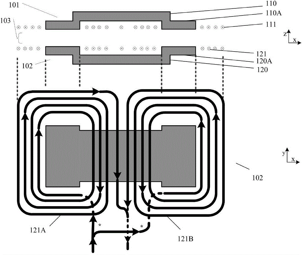
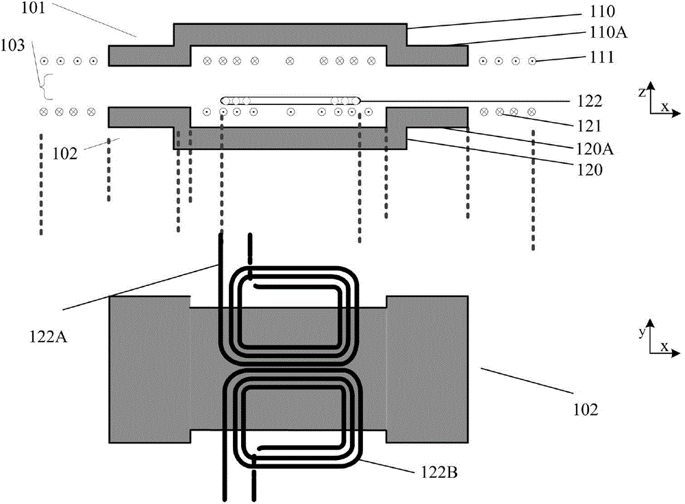
[0066] figure 2 It is a schematic structural diagram of the first embodiment of the non-contact transformer of the present invention, as figure 2 As shown, in the first embodiment, the structures of the primary side magnetic core 110 and the secondary side magnetic core 120 are two side columns (the primary side magnetic core side column 110A and the secondary side magnetic core side column 120A) and the bottom expands outward along the side The edge extension type, and the primary winding 111 is formed by two parts of the windings wound on the two magnetic core side columns in series in the forward direction or in parallel on different sides; the secondary winding includes the secondary main winding 121 ( figure 2 not shown in the lower figure) and an additional auxiliary winding 122. Thus forming the non-contact transformer with additional auxiliary winding of the present invention. Among them, the primary winding, secondary main winding, and auxiliary winding can be wound...
Embodiment 2
[0071] image 3 It is a schematic structural diagram of the second embodiment of the non-contact transformer of the present invention, as image 3As shown, in the second embodiment, the structure of the primary side magnetic core 110 is an edge expansion type in which the bottom of the two side columns (primary side magnetic core side column 110A) expands outward along the side, and the basic shape of the secondary side magnetic core is a cross structure, in which in the x direction, the edge-expanded characteristic structure in which the bottom of the two-side columns (secondary side magnetic core side column 120A) expands outward along the side is adopted, and the magnetic core part (120B) of the secondary side in the y-direction can also adopt edge expansion type structure. The entire magnetic core can be made of a whole magnetic core or multiple magnetic cores spliced together, that is, an array-type magnetic core structure is adopted, and the x-direction magnetic cores...
Embodiment 3
[0075] Figure 4 It is a structural schematic diagram of the third embodiment of the non-contact transformer of the present invention, as Figure 4 As shown, in the fourth embodiment, the structures of the primary side magnetic core 110 and the secondary side magnetic core 120 are two side columns (the primary side magnetic core side column 110A and the secondary side magnetic core side column 120A) and the bottom expands outward along the side The edge extension type, and the primary winding 111 is formed by two parts of the windings wound on the two magnetic core side columns in series in the forward direction or in parallel on different sides; the secondary winding includes the secondary main winding 121 ( Figure 4 not shown in the lower figure) and an additional auxiliary winding 322. Thus forming the non-contact transformer with additional auxiliary winding of the present invention.
[0076] The auxiliary winding 322 is divided into two sections. The two sections of wi...
PUM
 Abstract
Description
Claims
Application Information
 - Generate Ideas
- Intellectual Property
- Life Sciences
- Materials
- Tech Scout
- Unparalleled Data Quality
- Higher Quality Content
- 60% Fewer Hallucinations
Browse by: Latest US Patents, China's latest patents, Technical Efficacy Thesaurus, Application Domain, Technology Topic, Popular Technical Reports.
© 2025 PatSnap. All rights reserved.Legal|Privacy policy|Modern Slavery Act Transparency Statement|Sitemap|About US| Contact US: help@patsnap.com


