
A kind of substrate and array substrate

A technology of array substrates and substrates, applied in nonlinear optics, instruments, optics, etc., can solve the problems of inconsistency in orientation film orientation, inconsistency in fiber orientation on the cloth surface, and unequal surface height in the driving area, and improve the inconsistency of groove orientation , Improve the effect of inconsistency and improve the display effect

Inactive Publication Date: 2017-12-19
BOE TECH GRP CO LTD +1
View PDF7 Cites 0 Cited by
  • Summary
  • Abstract
  • Description
  • Claims
  • Application Information

AI Technical Summary

Problems solved by technology

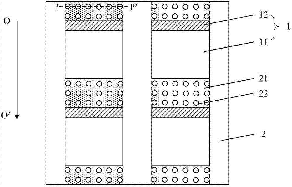
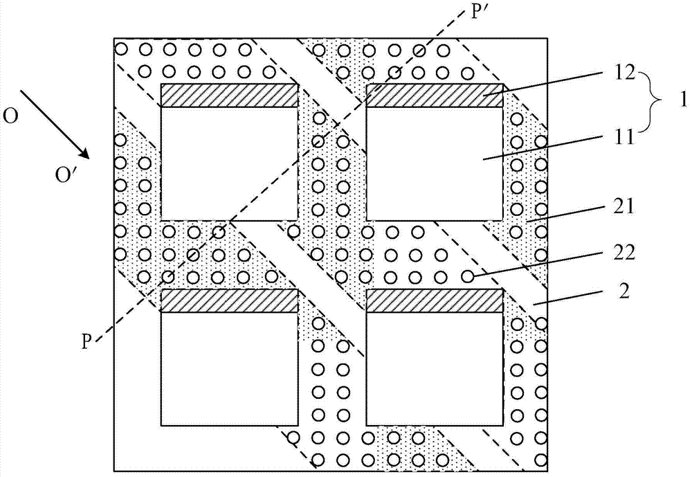
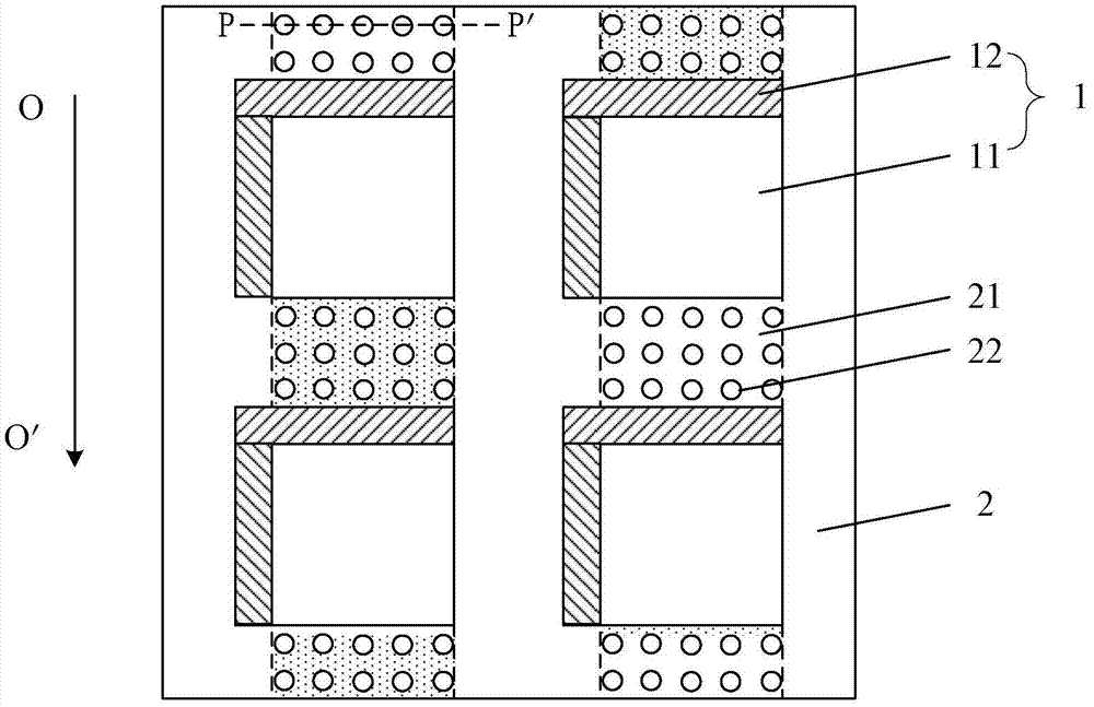
[0004] The inventors have found that the thicknesses of different regions in the driving region are different from each other. For example, the electrical detection region needs to insert a probe during the electrical detection process, and its thickness is relatively large, while the thickness of the blank region is the smallest, and the thickness of other regions is between the electrical detection region and the electrical detection region. Between the area and the blank area, so that the surface of the driving area is uneven. During the orientation friction process, when the cloth passes through the driving area many times, the surface of the cloth will be damaged. For example, the fibers on the surface of the cloth are not in the same direction; It is parallel to or at an angle of 45° to the extension direction of the data line. Therefore, the part of the fabric in which the fiber direction is inconsistent will also pass through the display area, resulting in inconsistent direction of the grooves on the surface of the alignment film after orientation rubbing, which in turn affects the liquid crystal display device. The display effect of

Method used


Image

  • A kind of substrate and array substrate
  • A kind of substrate and array substrate
  • A kind of substrate and array substrate

Examples


Embodiment Construction

[0025] The following will clearly and completely describe the technical solutions in the embodiments of the present invention with reference to the accompanying drawings in the embodiments of the present invention. Obviously, the described embodiments are only some, not all, embodiments of the present invention. Based on the embodiments of the present invention, all other embodiments obtained by persons of ordinary skill in the art without creative efforts fall within the protection scope of the present invention.

[0026] Embodiments of the present invention provide a substrate, such as Figure 1-4 As shown, the substrate includes at least one array substrate 1, and the periphery of each array substrate 1 on the substrate is provided with a spacer area 2, and each array substrate 1 includes a display area 11 and a driving area 12 located at the edge of the display area 11, the interval The area 2 includes a first area and a second area (not shown in the figure), the first are...


PUM


Abstract

The invention discloses a substrate and an array substrate, which relate to the field of display technology and can improve the problem of inconsistency in direction of grooves on the surface of an alignment film after alignment rubbing. The substrate provided by the embodiment of the present invention includes at least one array substrate, each of the array substrates on the substrate is provided with a spacer area around the periphery, and each of the array substrates includes a display area and a driving area located at the edge of the display area, the The interval area includes a first area and a second area, the first area is located in the direction in which the drive area extends along the orientation rubbing direction, and the second area is located in the direction in which the display area extends along the orientation rubbing direction. A plurality of via holes are distributed in the overlapping area of ​​the first area and the second area, and the diameter of the via holes is larger than the diameter of the fibers of the oriented friction cloth.

Description

technical field [0001] The present invention relates to the field of display technology, in particular to a substrate and an array substrate. Background technique [0002] The liquid crystal display device includes an array substrate, and the array substrate includes a display area and a drive area located at the edge of the display area, wherein the display area is provided with intersecting gate lines and data lines; the drive area is provided with data lines located in the extending direction of the data lines. Signal binding area, data line lead connecting data line and data signal binding area, gate signal binding area located in the extending direction of gate line or located in the extending direction of data line, connecting gate line and gate signal binding area The gate line leads in a fixed area, the electrical detection area located at both ends of the driving area, and the blank area without any components. [0003] In addition, an alignment film is also provid...

Claims


Application Information

Patent Timeline
Patent Type & Authority Patents(China)
IPC IPC(8): G02F1/1337G02F1/1362
CPCG02F1/133707G02F1/133784G02F1/136227G02F1/1337G02F1/13336G02F1/133345G02F1/13439G02F1/1368
Inventor 董廷泽黄东升张千
Owner BOE TECH GRP CO LTD
Learn More