
Static loading test device for missile wing

A test device and static loading technology, which is applied in the direction of applying stable tension/pressure to test the strength of materials, etc., can solve the problems of complex structure of electro-hydraulic servo loading device, structural damage of the elastic wing test piece, and high safety hazards. The effect of ensuring the consistency of the test state, improving the automation level and operation efficiency, and reducing the operation intensity

Inactive Publication Date: 2015-06-03
中国航天科工集团第六研究院四十一所
View PDF16 Cites 8 Cited by
  • Summary
  • Abstract
  • Description
  • Claims
  • Application Information

AI Technical Summary

Problems solved by technology

The electro-hydraulic servo loading device has a complex structure, high cost, inconvenient maintenance, and requires professionals to set parameters and operate; while the crane hoisting heavy block suspension loading device has a simple structure, but it needs to be disassembled repeatedly and coordinated by multiple people, which is time-consuming and laborious , especially when the operator is under the crane and the heavy block during operation, the safety hazard is relatively high
In addition, the impact or vibration load generated when the crane lifts the weight may be far greater than the test requirements, which will cause unnecessary structural damage to the wing test piece

Method used


Image

  • Static loading test device for missile wing
  • Static loading test device for missile wing
  • Static loading test device for missile wing

Examples


Embodiment Construction

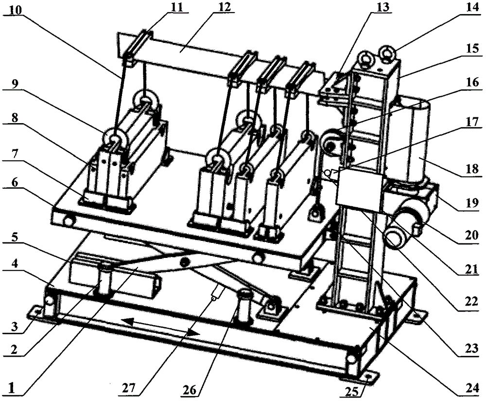
[0058] figure 1 It is the overall structure diagram of the static loading test device of the elastic wing of the present invention, which is mainly composed of the scissor mechanism 1, the buffer pillar 2, the basic platform 4, the trough guide rail 5, the lifting platform 6, the weight 8, and the load-bearing soft sling 10 , Wrap belt 11, elastic wing 12, elastic wing clamp 13, bearing column 15, fixed pulley 16, upper limit travel switch 17, reel mechanism 18, two-stage gear reducer 19, electric motor 20, electric control box 21, wire rope Cable 22, guide wheels 23, cover plate 24, lower limit travel switch 27 and other components.

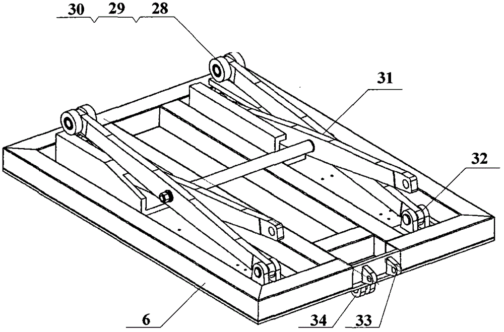
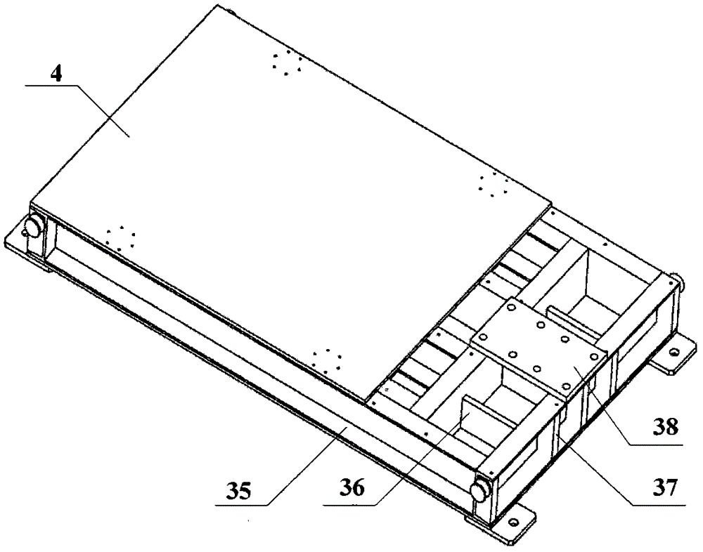
[0059] In specific implementation, such as figure 1 with 2 As shown, the structural features and connection relationships of the main components are as follows:

[0060] ①The foundation platform 4 is formed by tailor-welding of several channel steel 35 and steel plates. The adapter plate 38 is welded on the side of the foundation platform 4, and the ...


PUM


Abstract

The invention belongs to static test devices for aerial bomb missile wings, and in particular relates to a static loading test device for a missile wing. The static loading test device comprises a scissor fork mechanism, a cushion supporting column, a foundation platform, four groove-shaped guide rails, a movable lifting platform, a heavy block, a force-bearing soft hoisting belt, a taping belt, a missile wing clamp, a force-bearing vertical column, a fixed pulley, a winding drum mechanism, a speed reducer, an electric motor, an electric control cabinet, a steel wire rope and a guide wheel, wherein two groove-shaped guide rails are arranged on the upper surface of the foundation platform, and the scissor fork mechanism is arranged on the upper surface of the foundation platform by virtue of two supporting bases; cushion supporting bases are symmetrically fixedly arranged on the periphery of the upper surface of the foundation platform; the other two groove-shaped guide rails are arranged on the lower surface of the movable lifting platform, and the scissor fork mechanism is connected to the lower surface of the movable lifting platform by virtue of another two supporting bases; and the scissor fork mechanism is in rolling contact with the groove-shaped guide rails. The test device disclosed by the invention is simple to operate, and ensures that the operation strength can be effectively reduced, the number of operating staff can be reduced, and the cost and maintenance fees can be lowered.

Description

Technical field [0001] The invention belongs to a static test device for an air missile wing, and in particular relates to a static loading test device for a missile wing. Background technique [0002] The wing is a crucial part of the extended range of the aerial missile, and its wing surface bears aerodynamic uniform load during flight. In the ground test, the aerodynamic load must be simulated to assess the performance of the missile wing. Generally, according to the principle of bending moment equivalence, multi-point concentrated loading is used to simulate the wind load when the missile wing is deployed. [0003] At present, the most commonly used wing loading methods at home and abroad mainly include electro-hydraulic servo loading and crane hoisting standard weight suspension loading, etc. The former requires power oil source, electro-hydraulic servo valve, servo actuator, load sensor and data The acquisition and control system constitutes a closed-loop mode to complete th...

Claims


Application Information

Patent Timeline
IPC IPC(8): G01N3/14
Inventor 李世忠张名城李先聚李恒靳向往李亮李金山
Owner 中国航天科工集团第六研究院四十一所
Learn More