Two-way bearing heavy load guide rail pair

A guide rail pair, guide rail technology, applied in the direction of bearings, shafts and bearings, linear motion bearings, etc., can solve the problems of limited application scope, increased size, and reduced stability.

Inactive Publication Date: 2015-06-03
ZHENGZHOU UNIV
View PDF11 Cites 5 Cited by
  • Summary
  • Abstract
  • Description
  • Claims
  • Application Information

AI Technical Summary

Problems solved by technology

[0003] Due to the structural limitation of the traditional rolling guide block, the guide rail block can only bear load in one direction. In order to realize the two-way load bearing, two guide rail blocks need to be stacked and installed in reverse, which greatly increases the size of the mechanism in the bearing direction and improves the stability. reduced, the scope of application is limited

Method used


Image

  • Two-way bearing heavy load guide rail pair
  • Two-way bearing heavy load guide rail pair
  • Two-way bearing heavy load guide rail pair

Examples


Embodiment Construction

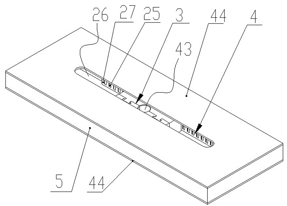
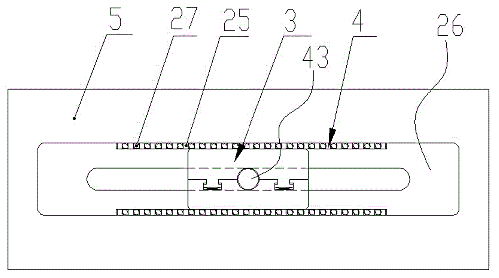
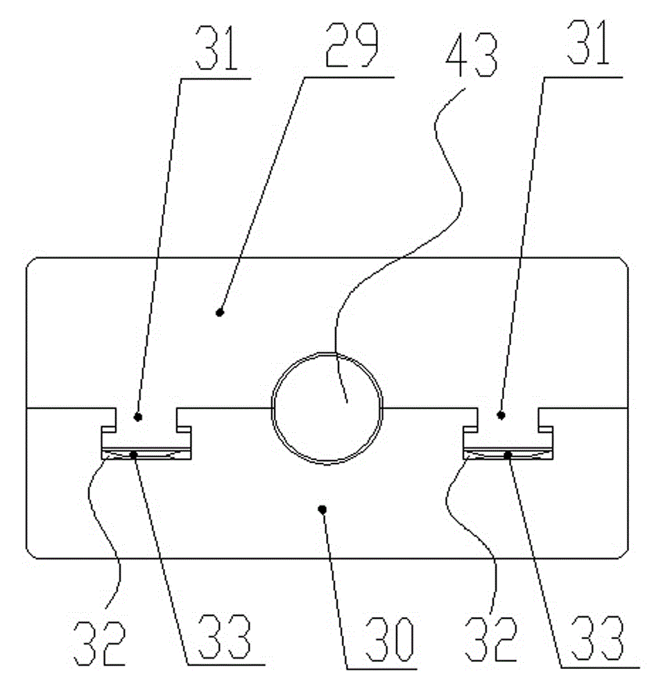
[0017] Combine below Figure 1 to Figure 4 The structure and working process of the present invention are further described.

[0018] A two-way force-bearing heavy-duty guide rail pair, which includes a guide rail frame body 5 provided with a guide rail groove 26, and a self-tensioning slider 3 matched with it is provided inside the rail groove 26, and the self-tensioning slider A roller row 4 is arranged between both sides of the block 3 and the inner wall of the guide rail groove 26, and the roller row 4 is composed of a roller row 27 and a roller cage 25, and the roller cage 27 is provided with a Roller rows 25 are matched with roller positioning holes arranged in a grid structure (not marked in the drawings), each roller of the roller row 25 is arranged in the roller positioning holes, and the rollers Both sides of the roller in the column positioning hole are rollingly connected with the self-tensioning slider 3 and the inner wall of the guide rail groove 26; the self-te...


PUM


Abstract

The invention discloses a two-way bearing heavy load guide rail pair. The guide rail pair comprises a guide rail frame provided with a guide rail groove, wherein a self-tensioning slide block matched with the guide rail groove is formed in the guide rail groove; pin roller rows are arranged between two sides of the self-tensioning slide block and the inner wall of the guide rail groove; the pin roller rows consist of pin roller columns and pin roller retainers; the self-tensioning slide block comprises a first slide block and a second slide block which can be separated from each other; a positioning boss is formed on the first slide block; a positioning groove matched with the positioning boss is formed in the second slide block; and the inner side of the first slide block and the inner side of the second slide block are connected in a matched mode by virtue of the positioning boss and the positioning groove. Two-way bearing of the mechanism is realized, and the two-way bearing heavy load guide rail pair disclosed by the invention has the advantages of high bearing capacity and compact structure.

Description

technical field [0001] The invention belongs to the technical field of guide rail pair structure, and in particular relates to a two-way force-bearing heavy-duty guide rail pair. Background technique [0002] The traditional heavy-duty rolling guide block generally includes: a slider body, a protective plate, an end cover, a guide piece, a roller and a retainer, and the rolling body performs a circular motion. The method of use is to install the rolling guide block on the guide rail surface of the moving parts. At least two guide rails are used for each guide rail. The number of guide rail blocks depends on the length of the guide rail and the size of the load. The matching guide rails are mostly inlaid steel quenching guide rails. When the moving part moves, the guide rail surface of the roller support part rolls between the body and at the same time rolls circularly around the body. The rolling guide block is characterized by high rigidity, large load-carrying capacity, a...

Claims


Application Information

Patent Timeline
IPC IPC(8): F16C29/04F16C29/08F16C29/12
Inventor 王建强张俊峰田野焦建国王建亮王海洋李政辛伟
Owner ZHENGZHOU UNIV
Why Eureka
Try Eureka