Nose structure and mustard tuber harvester comprising same
A harvester and machine head technology, applied in the mustard harvester field, can solve the problems of high labor intensity, inconvenient collection and storage, and difficult separation
- Summary
- Abstract
- Description
- Claims
- Application Information
AI Technical Summary
Problems solved by technology
Method used
Image
Examples
Embodiment 1
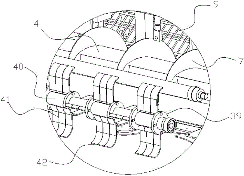
[0035] Embodiment 1: as figure 1 , figure 2 , image 3 , Figure 4 , Figure 5 , Figure 6 , Figure 7 In the shown embodiment, a machine head structure includes a gear set mechanism driven by a hydraulic motor and located on the front frame of the machine head, as well as a leaf beating mechanism, a preliminary feeding mechanism, and a transitional feeding mechanism:
[0036] The gear set mechanism includes an auger power gear 1 and a knife power gear 2;
[0037] The leaf beating mechanism includes a knife cover 3 with a lower opening, an auger shaft 4 coaxial with the auger power gear, and a rotary knife shaft 5 coaxial with the knife power gear. The rotary knife shaft is provided with a plurality of Leaf beating knife 6, described auger shaft is provided with leaf-feeding auger 7, described rotating knife shaft, beating leaf knife are in the knife cover, and described knife cover is provided with recovery cover 8, so The recovery cover communicates with the rear end...
Embodiment 2
[0048] Embodiment 2: the basic structure and implementation mode of this embodiment are the same as embodiment 1, and its difference is, as Figure 8 , Figure 9 As shown, an external rotating leaf spreading device is provided beside the horizontal leaf row hole, and the external rotating leaf spreading device includes an outer row leaf cover 45 and an outer row leaf rotating shaft 46, and the outer row leaf rotating shaft is connected to the outer row The impeller 47, the outer leaf bevel gear 48 is arranged on the outer leaf rotating shaft, the transmission bevel gear is provided on the auger shaft, the outer leaf bevel gear meshes with the transmission bevel gear, and the The outer row of blade rotating shafts is located on the outer row of blade bearings 49 . The vegetable leaves discharged from the horizontal leaf hole will enter the outer row leaf cover, and will be scattered outwards under the drive of the outer row impeller.
Embodiment 3
[0049] Embodiment 3: the basic structure and implementation mode of this embodiment are the same as embodiment 1, and its difference is, as Figure 10 , Figure 11 , Figure 12 As shown, the fuselage is provided with a material distribution device, and the material distribution device includes a guide arc plate 32, a material distribution arc plate 33, an arc-shaped material distribution spring net 34, and a material distribution adjustment cylinder 35. The arc-shaped material distribution elastic net is connected on the material distribution arc plate, and the space between the material distribution arc plate and the arc-shaped material distribution elastic net is the screening part 36, and the described material distribution arc plate is attached to the guide arc On the board, the radian of the bottom surface of the material distribution arc plate matches the top surface curvature of the guide arc plate, the piston rod of the material distribution adjustment cylinder is pro...
PUM
 Abstract
Description
Claims
Application Information
 - R&D Engineer
- R&D Manager
- IP Professional
- Industry Leading Data Capabilities
- Powerful AI technology
- Patent DNA Extraction
Browse by: Latest US Patents, China's latest patents, Technical Efficacy Thesaurus, Application Domain, Technology Topic, Popular Technical Reports.
© 2024 PatSnap. All rights reserved.Legal|Privacy policy|Modern Slavery Act Transparency Statement|Sitemap|About US| Contact US: help@patsnap.com


