
Cutting insert and cutting edge replacement-type rotating cutting instrument

A technology for cutting blades and blades, which is applied in the direction of milling cutting blades, manufacturing tools, milling cutters, etc., and can solve problems such as high-frequency vibration, insufficient overall strength, and thin cutting blades

Active Publication Date: 2015-05-27
TUNGALOY CORP
View PDF9 Cites 4 Cited by
  • Summary
  • Abstract
  • Description
  • Claims
  • Application Information

AI Technical Summary

Problems solved by technology

Furthermore, if the cutting insert described in each of Patent Documents 1 to 3 is miniaturized as it is, the cutting insert will be too thin, its overall strength will be insufficient, and high-frequency vibration will be more likely to occur.

Method used


Image

  • Cutting insert and cutting edge replacement-type rotating cutting instrument
  • Cutting insert and cutting edge replacement-type rotating cutting instrument
  • Cutting insert and cutting edge replacement-type rotating cutting instrument

Examples


Embodiment Construction

[0038] Hereinafter, embodiments of the present invention will be described in detail with reference to the drawings.

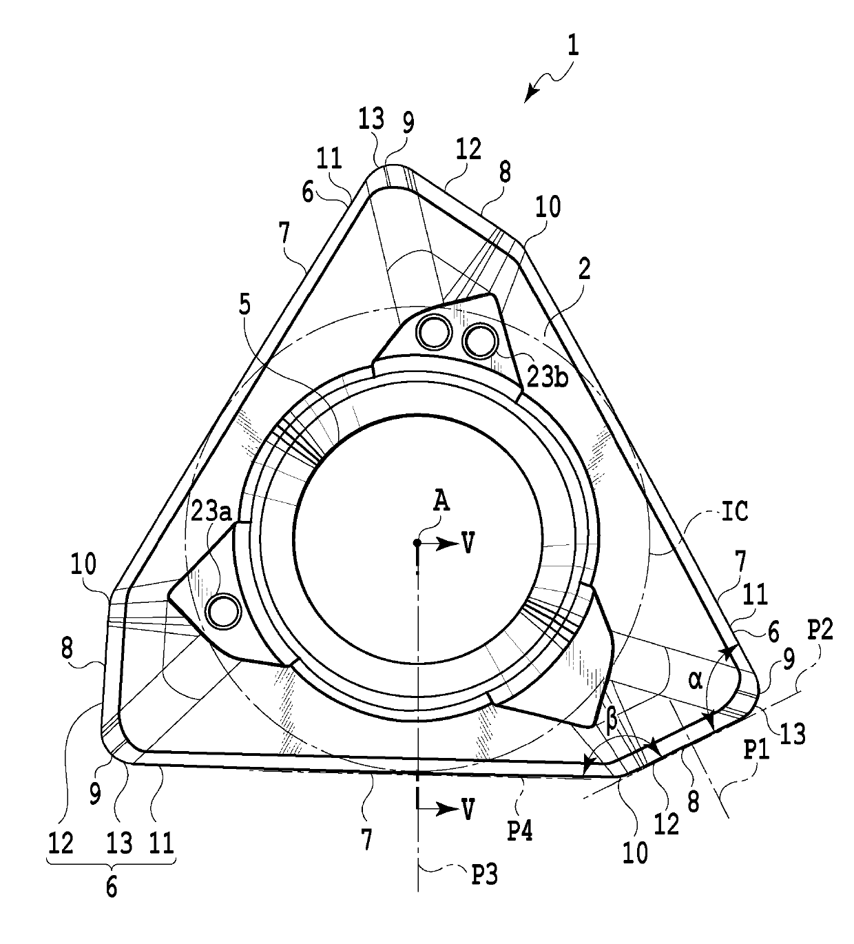
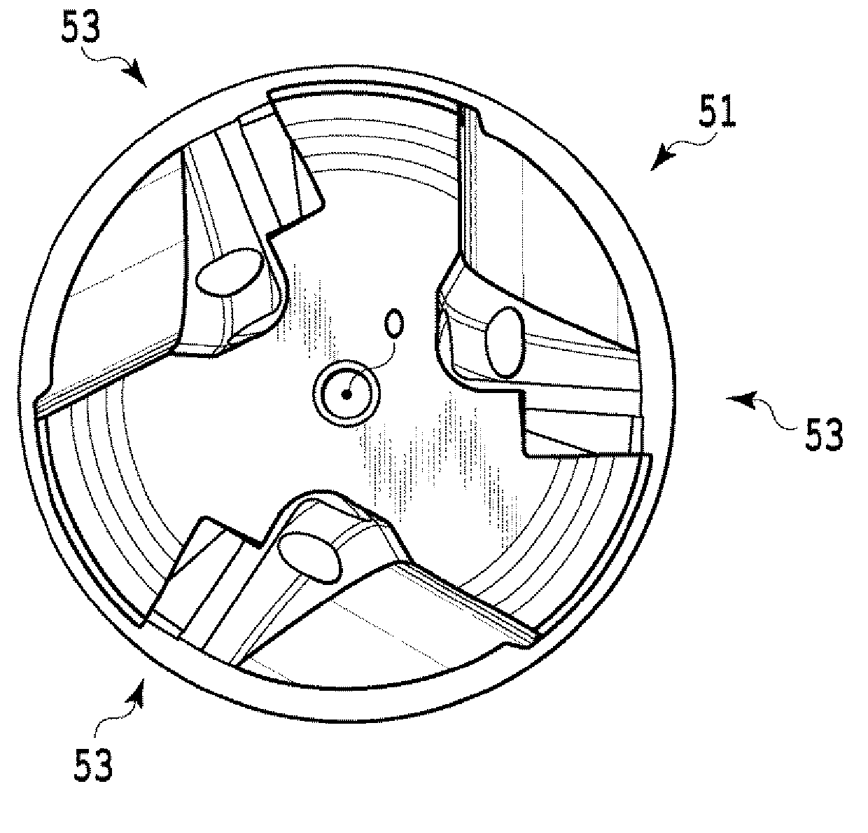
[0039] The cutting insert 1 of the present embodiment is as Figures 1 to 4 As shown, there are two end faces 2, 3 which are opposite or face opposite sides of each other, and a peripheral side 4 which connects them or extends between them. Below, will figure 1 as well as figure 2 One end surface (corresponding to the first end surface of the present invention) 2 facing upward is referred to as the upper surface, and the other end surface (corresponding to the second end surface of the present invention) 3 is referred to as the lower surface. In addition, based on the relative positional relationship between the upper surface and the lower surface, the words "upper" and "lower" may be used in the following description. However, these terms are not intended to limit the orientation or position of the cutting insert, but are used to facilitate understanding,...


PUM


Abstract

An objective of the present invention is to provide a cutting insert (1) which is suitable for 90° shoulder cutting. A cutting insert (1) comprises: two first and second end faces (2, 3); a circumference side face (4) which extends therebetween; and a cutting blade (6) which is formed at an intersection ridgeline part of the first end face and the circumference side face. The cutting blade (6) is formed such that the first end face (2) functions as a rake face and a portion of the circumference side face (4) functions as a flank face. Side face parts (15) of the circumference side face, which are adjacent to at least a portion the cutting blade (6), comprise, in order from the first end face side toward the second end face side, a first flank face part (18) which is adjacent to the cutting blade, a second flank face part (19), a third flank face part (20), and a fourth flank face part (21).

Description

technical field [0001] The present invention relates to a cutting insert and a rotary cutting tool with replaceable bits. More specifically, the present invention relates to a cutting insert used for 90° shoulder cutting, and a head replaceable rotary cutting tool in which the insert is detachably mounted. Background technique [0002] Conventionally, 90° shoulder cutting for the purpose of cutting the machined side wall surface of the workpiece at right angles to the machined bottom wall surface has been performed using a rotary cutting tool of a replaceable tip type. Examples of cutting inserts used in such cutting processing are disclosed in Patent Documents 1 to 3. The cutting inserts disclosed in these patent documents all have a structure in which the relief surface connected to the main cutting edge is divided into three segments in the direction of the center line of the insert. Specifically, the relief surface connected to the main cutting edge is composed of a fi...

Claims


Application Information

Patent Timeline
IPC IPC(8): B23C5/20B23C5/10
CPCB23C5/109B23C5/20B23C2200/0405B23C2200/161B23C2200/203B23C2210/0435B23C2200/0411B23C2200/125B23C2200/208B23C2210/66B23C2250/16Y10T407/1924Y10T407/23B23C5/202
Inventor 盐田雄介阿曾孝洋
Owner TUNGALOY CORP
Learn More