Power generation device and power generation system
A technology for a power generation device and a friction generator, which is applied in the field of electric energy, can solve the problems of the friction generator being unfavorable to collect wind energy, and the efficiency of wind power generation is low, and achieve the effects of improving the efficiency of wind power generation and reducing the weight.
- Summary
- Abstract
- Description
- Claims
- Application Information
AI Technical Summary
Problems solved by technology
Method used
Image
Examples
example 1
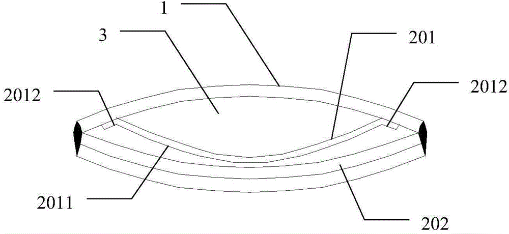
[0051] Figure 2a It is a schematic front cross-sectional view of the power generation device of Example 1 in Embodiment 1 of the present invention, as Figure 2aAs shown, the first electrode 211 is a free layer, and the first polymer insulating layer 212 and the second electrode 213 are stacked together to form a fixed layer; the first electrode 211 has two connections respectively located at its two ends. part and the extension part between the two connection parts, wherein the friction interface is formed between the extension part of the first electrode 211 and the first polymer insulating layer 212; the first electrode 211 is connected to the windsock through the two connection parts The inner wall of 1; the two ends of the first polymer insulating layer 212 and the second electrode 213 that are stacked together are fixedly installed on the inner wall of the windsock 1; the first electrode 211 is located on the first polymer insulating layer 212 And between the inner wal...
example 2
[0056] Figure 2b It is a schematic front cross-sectional view of the power generation device of Example 2 in Embodiment 1 of the present invention, as Figure 2b As shown, the first electrode 211 and the first polymer insulating layer 212 are stacked together to form a free layer, and the second electrode 213 is a fixed layer; the free layer has two connecting parts respectively located at its two ends and An extension between the two connecting parts, wherein a friction interface is formed between the first high molecular polymer insulating layer 212 and the second electrode 213; the first electrode 211 and the first high molecular polymer insulating layer 212 are connected by two The part is connected to the inner wall of the windsock 1; the two ends of the second electrode 213 are fixedly installed on the inner wall of the windsock 1; the free layer formed by the first electrode 211 and the first polymer insulating layer 212 is located between the second electrode 213 and ...
example 3
[0062] Figure 2c It is a schematic front cross-sectional view of the power generation device of Example 3 in Embodiment 1 of the present invention, as Figure 2c As shown, the first electrode 211 and the first high molecular polymer insulating layer 212 are free layers separated by two layers, and the second electrode 213 is a fixed layer; the first high molecular polymer insulating layer 212 and the first electrode 211 A friction interface is formed between the electrodes and / or between the first polymer insulating layer 212 and the second electrode 213 . The first electrode 211 and the first high molecular polymer insulating layer 212 each have two connecting portions at both ends and an extension between the two connecting portions; the first electrode 211 and the first high molecular polymer insulating layer 212 can be The two connecting parts are respectively connected to the inner wall of the windsock 1 , or the two connecting parts can be correspondingly connected tog...
PUM
 Abstract
Description
Claims
Application Information
 - R&D
- Intellectual Property
- Life Sciences
- Materials
- Tech Scout
- Unparalleled Data Quality
- Higher Quality Content
- 60% Fewer Hallucinations
Browse by: Latest US Patents, China's latest patents, Technical Efficacy Thesaurus, Application Domain, Technology Topic, Popular Technical Reports.
© 2025 PatSnap. All rights reserved.Legal|Privacy policy|Modern Slavery Act Transparency Statement|Sitemap|About US| Contact US: help@patsnap.com


