
Distribution transform terminal for power distribution automation

A technology for power distribution automation and distribution transformer terminals, applied to electrical components, circuit devices, and AC networks to reduce harmonics/ripples, etc., can solve problems such as poor reliability of power supply and unstable operation of distribution transformers, and achieve reliable power supply performance, improve the level of distribution network planning, and achieve stable operation

Inactive Publication Date: 2015-05-27
HANGZHOU SHENHAO TECH
View PDF3 Cites 0 Cited by
  • Summary
  • Abstract
  • Description
  • Claims
  • Application Information

AI Technical Summary

Problems solved by technology

[0003] The present invention provides a power distribution automation distribution transformer terminal to solve the problems of unstable operation of distribution transformers and poor reliability of power supply in the traditional power distribution system in the above-mentioned background technology

Method used


Image

  • Distribution transform terminal for power distribution automation
  • Distribution transform terminal for power distribution automation
  • Distribution transform terminal for power distribution automation

Examples


Embodiment

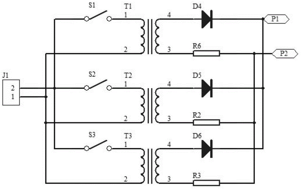
[0023] This embodiment includes: a main control unit, a distribution transformer terminal, a low-voltage reactive power compensation unit, and a power supply unit.

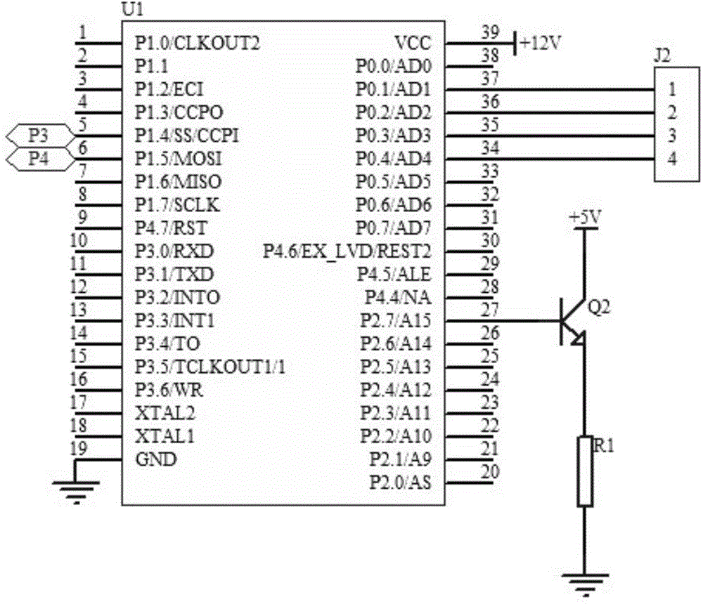
[0024] figure 1 Among them, the distribution transformer terminal is connected to the low-voltage reactive power compensation unit, the low-voltage reactive power compensation unit is connected to the main control unit, and the power supply unit is connected to the main control unit. The power supply unit includes voltage +12V and voltage +5V.

[0025] figure 2 Among them, the main control unit includes a chip U1, a transistor Q2, a resistor R1, and an output interface J2. The pin 19 of the chip U1 is grounded, its pin 27 is connected to the base of the transistor Q2, and its pin 34 is connected to the pin 4 of the output interface J2. , its pin 35 is connected to the pin 3 of the output interface J2, its pin 36 is connected to the pin 2 of the output interface J2, its pin 37 is connected to the pin 1 of the out...


PUM


Abstract

The invention belongs to the technical field of power distribution, and particularly relates to a distribution transform terminal for power distribution automation. The distribution transform terminal comprises a main control unit, a distribution transform terminal body, a low-voltage reactive power compensation unit and a power source unit, wherein the distribution transform terminal body is connected with the low-voltage reactive power compensation unit; the low-voltage reactive power compensation unit is connected with the main control unit; the power source unit is connected with the main control, and comprises a 12 V power source and a 5 V power source; the main control unit comprises a chip U1; the pin 19 of the chip U1 is earthed; the emitting electrode of a triode Q2 is connected with one end of a resistor R1; the collecting electrode of the triode Q2 is connected with the 5 V power source; the other end of the resistor R1 is earthed. The distribution transform terminal has the advantages that a low-voltage reactive power compensation mode is adopted, so that the requirement for quick load changing can be met, reactive power compensation can be quick and dynamic, and power connection can be realized in a distributed manner. Therefore, a distribution transformer can operate more stably, and power supply can be more reliable and safer.

Description

technical field [0001] The invention belongs to the technical field of power distribution, and in particular relates to a distribution transformer terminal for power distribution automation. Background technique [0002] In the power supply and distribution system, the distribution transformer is the power equipment that directly distributes the voltage to the low-voltage users. Its operating data is an important part of the basic data of the entire distribution network, including: three-phase voltage, three-phase current, three-phase Phase active (reactive) power, power factor, frequency, oil temperature (humidity), etc. Whether these data are normal or not is an important reflection of whether the distribution transformer is running well. Therefore, real-time monitoring of abnormal conditions in the operation of distribution transformers and timely control or resolution can achieve stable and optimal operation of the power grid. However, in the traditional distribution sy...

Claims


Application Information

Patent Timeline
Patent Type & Authority Applications(China)
IPC IPC(8): H02J13/00H02J3/18H02J3/01
CPCY02E40/30Y02E40/40
Inventor 陈如申黎勇跃
Owner HANGZHOU SHENHAO TECH
Learn More