A multifunctional friction and wear testing machine
A friction and wear test, multi-functional technology, applied in the direction of testing wear resistance, using mechanical devices, measuring devices, etc., can solve the problems of high cost and complex structure, and achieve the effect of complete functions, low cost and simple structure
- Summary
- Abstract
- Description
- Claims
- Application Information
AI Technical Summary
Problems solved by technology
Method used
Image

Examples
Embodiment 1
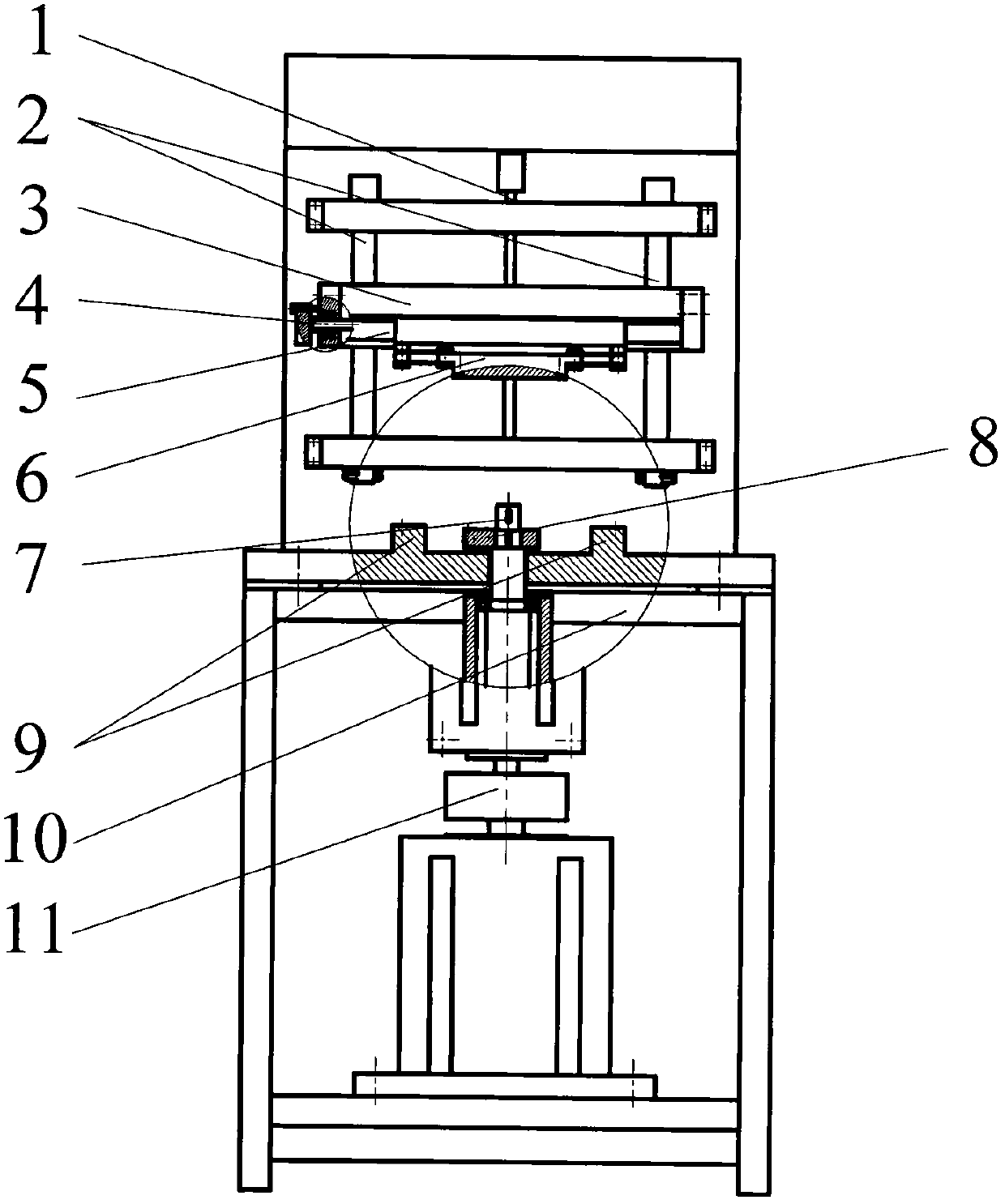
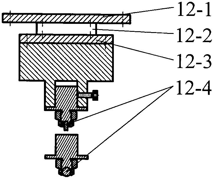
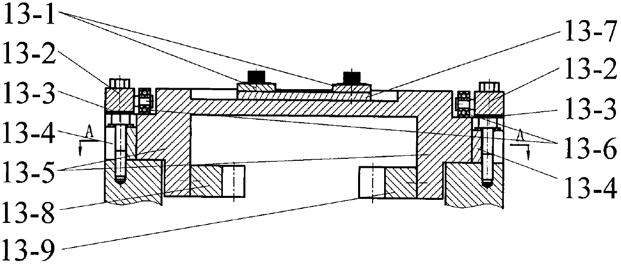
[0026] Embodiment one: if figure 1 As shown, a multifunctional friction and wear testing machine, the body includes a vertical screw 1, a vertical guide column 2, a cantilever bracket 3, a horizontal screw 4, a horizontal guide column 5, an upper friction pair coupling seat 6, a rotating main shaft 7, and Complete gear 8, rectangular guide rail 9, frame 10, synchronous belt drive 11. If the test machine is used as Image 6 For the tribological test of the upper friction pair 12-4 on the pin or ball and the lower friction pair 13-7 shown, before the test, the upper friction pair assembly 12 on the pin or ball needs to be fixed on the upper friction pair coupling seat 6 with screws, And place the friction pair 12-4 on the pin or the ball in the friction pair assembly 12 on the pin or the ball, fasten with a nut; place the reciprocating lower friction pair assembly 13 on the rectangular guide rail 9 of the frame 10, and make the reciprocating The left rack 13-8 in the lower fri...
Embodiment 2
[0027] Embodiment two: if use testing machine to carry out such as Figure 9 In the tribological test of the friction pair 14-10 on the end face and the friction pair 15-1 on the lower end face, it is necessary to connect the pin or ball upper friction pair assembly 12 installed on the upper friction pair coupling seat 6 and the friction pair assembly 12 installed on the rectangular guide rail 9. The reciprocating lower friction pair assembly 13 is removed, and then the friction pair assembly 14 on the end face is fixed on the upper friction pair coupling seat 6 with screws, the lower friction pair assembly 15 on the end face is set on the rotating main shaft 7, and the friction pair 14 on the end face -10 and the friction pair 15-1 under the end face are respectively placed in the friction pair assembly 14 on the end face and the friction pair assembly 15 under the end face, and fastened with set screws. Among them, the friction pair assembly 14 on the end face is composed of...
Embodiment 3
[0028] Embodiment three: if use testing machine to carry out such as Figure 11 For the tribological test of the upper friction pair 12-4 of the pin or ball and the lower friction pair 16-1 of the rotating disk, it is necessary to install the friction pair assembly 14 on the end surface of the upper friction pair coupling seat 6 and the friction pair assembly 14 on the rotating main shaft 7 Disassemble the friction pair assembly 15 under the end face, and then put the friction pair assembly 16 under the rotating disk on the rotating main shaft 7, and place the friction pair 16-1 under the rotating disk in the friction pair assembly 16 under the rotating disk, and use a tightening Screw fastening; the friction pair assembly 12 on the pin or the ball is fixed on the upper friction pair connection seat 6 with screws, and the friction pair 12-4 on the pin or the ball is placed in the friction pair assembly 12 on the pin or the ball, and the friction pair assembly 12 is fixed with t...
PUM
 Abstract
Description
Claims
Application Information
 - R&D
- Intellectual Property
- Life Sciences
- Materials
- Tech Scout
- Unparalleled Data Quality
- Higher Quality Content
- 60% Fewer Hallucinations
Browse by: Latest US Patents, China's latest patents, Technical Efficacy Thesaurus, Application Domain, Technology Topic, Popular Technical Reports.
© 2025 PatSnap. All rights reserved.Legal|Privacy policy|Modern Slavery Act Transparency Statement|Sitemap|About US| Contact US: help@patsnap.com