
Valve plate feeding mechanism

A technology of feeding mechanism and valve plate, applied in the direction of conveyor objects, metal processing, metal processing equipment, etc., can solve the problems of many workers, difficult accurate measurement, high production cost, etc.

Active Publication Date: 2015-05-27
WUXI HUIFATE PRECISION MACHINERY
View PDF5 Cites 2 Cited by
  • Summary
  • Abstract
  • Description
  • Claims
  • Application Information

AI Technical Summary

Problems solved by technology

[0002] At present, it is known in the automobile gas shock absorber production industry that the valve plate assembly of the automobile gas shock absorber compression / recovery valve is manually operated. to the next station, but the manual operation has the following problems, one is that it requires many workers, the production cost is high, and the efficiency is low, and the other is that it is difficult to measure accurately

Method used


Image

  • Valve plate feeding mechanism
  • Valve plate feeding mechanism

Examples


Embodiment Construction

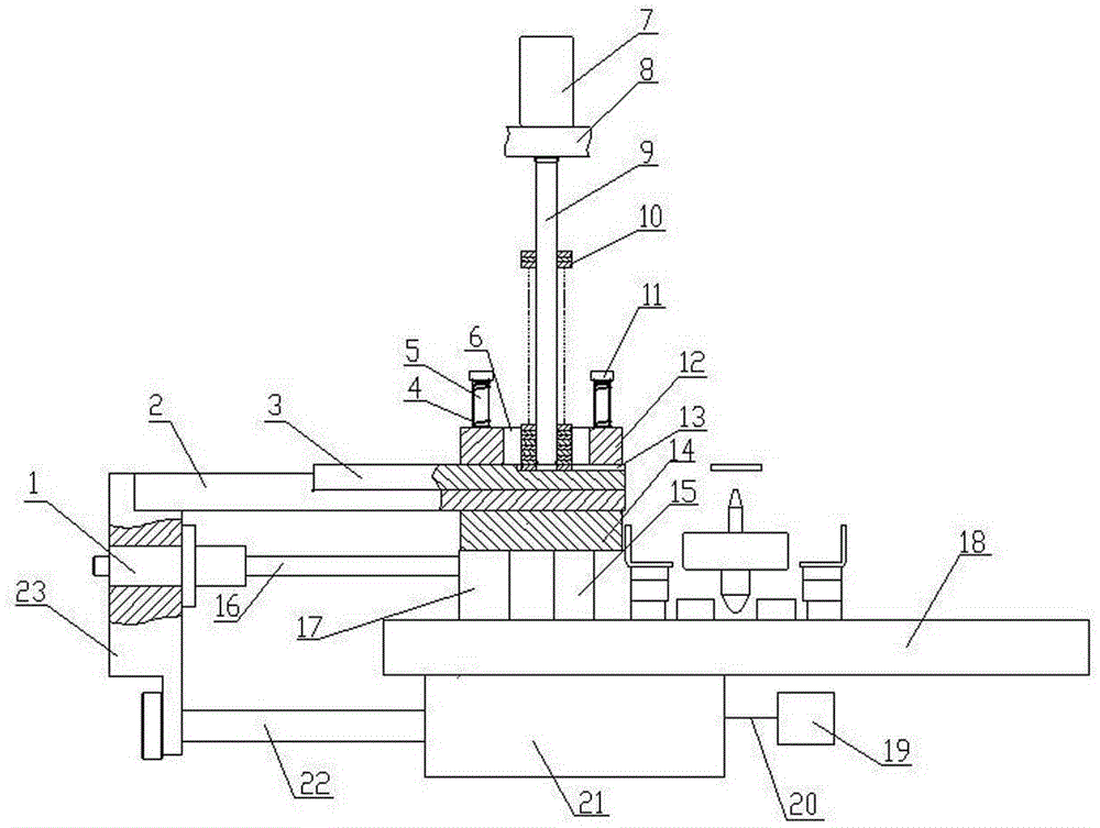
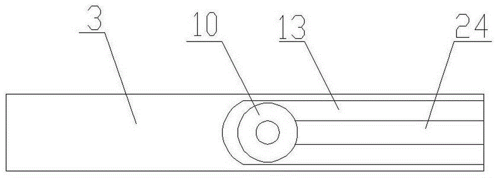
[0014] Such as figure 1 and figure 2 As shown, the valve feeding mechanism of the present invention includes a base plate 18 and a controller 19 . A lower positioning block 14 is arranged on the base plate 18 , and the lower positioning block is fixed on the base plate 18 by means of a support plate 17 and a column 15 . The upper positioning block 12 is arranged on the lower positioning block 14, and the edge of the lower positioning block 14 is processed with four vertical screw holes, and the edge of the upper positioning block 12 is processed with four vertical through holes. The number of vertical through holes on the hole and the upper positioning block 12 is equal and corresponding, and a first guide rod 5 is arranged between the corresponding vertical through holes and the vertical screw holes, and the lower end of the first guide rod 5 is processed with threads and Screw in the vertical screw hole on the lower positioning block 14 after passing through the correspon...


PUM


Abstract

The invention discloses a valve plate feeding mechanism, which is characterized by comprising a base plate and a controller, wherein a lower positioning block and an upper positioning block are arranged on the base plate; the edge of each of the lower positioning block and the upper positioning block is connected with a guide rod. A vertical hole is formed in the center of the upper positioning block; a valve plate installation rod is arranged above the upper positioning block; the lower end of the valve plate installation rod extends into the vertical hole of the upper positioning block. The adjacent faces of the upper positioning block and the lower positioning block are provided with long slots which extend to the corresponding edges; the two long slots correspond to each other; each long slot is internally provided with a valve plate pushing plate. A longitudinal shallow slot, which extends to one end of the valve plate pushing plate and is fitted with a valve plate, is formed in the position, corresponding to the vertical hole, at the upper surface of the valve plate pushing plate. One end, without the no shallow, of the valve plate pushing plate is connected with a pushing rod. An air cylinder is arranged below the base plate; a vertical plate is arranged on the frame at the outer end of the pushing rod and the piston rod of the air cylinder; the piston rod and the outer end of the pushing rod are both connected with the vertical plate. The controller is connected with the air cylinder. By employment of the valve plate feeding mechanism, the needed labor is less, the production cost is low, the production efficiency is high, and the measurement is accurate. The valve plate feeding mechanism is suitable for assembly of the valve plate of a compression / rebuilt valve on an automobile air-charging damper.

Description

technical field [0001] The invention relates to a valve sheet feeding mechanism. Specifically, it is a device for metering while sending the valve plate of the compression recovery valve for the automobile gas shock absorber to the next station in an orderly manner. Background technique [0002] At present, it is known in the automobile gas shock absorber production industry that the valve plate assembly of the automobile gas shock absorber compression / recovery valve is manually operated. to the next station, but the manual operation has the following problems. First, it requires many workers, high production costs, and low efficiency. Second, it is difficult to measure accurately. Contents of the invention [0003] The problem to be solved by the present invention is to provide a valve sheet feeding mechanism. Adopting the valve plate feeding mechanism can not only reduce the number of workers, reduce production costs, improve production efficiency, but also perform acc...

Claims


Application Information

Patent Timeline
Patent Type & Authority Applications(China)
IPC IPC(8): B65G47/06B23P19/00
Inventor 谢小贤
Owner WUXI HUIFATE PRECISION MACHINERY
Learn More